Stapling machine

A technology of stapler and top plate, applied in the direction of nailing staple tools, manufacturing tools, etc., can solve the problems of not necessarily good results, troublesome, using a lot of effort, etc.

Inactive Publication Date: 2013-02-13
陈群
View PDF6 Cites 1 Cited by
  • Summary
  • Abstract
  • Description
  • Claims
  • Application Information

AI Technical Summary

Problems solved by technology

[0002] Stapler is a necessary office supplies for office work. It is used frequently. It is very convenient for binding some office documents with few papers, but it is more

Method used


Image

  • Stapling machine
  • Stapling machine

Examples


Example Embodiment

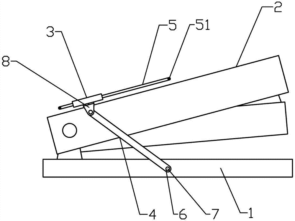
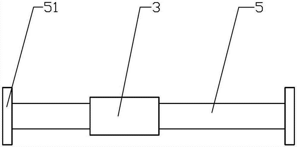
[0009] Such as figure 1 As shown, the stapler of the present invention includes a base 1 and a top plate 2. A cylindrical body 3 with a long and narrow cross section and open ends is placed above the top plate 2, and the axis of the cylindrical body 3 is parallel to the top plate 2. A hinge 8 is connected to both sides of the cylinder 3, a bracket 4 is hinged below the hinge 8, the other end of one bracket 4 is hinged to the middle of the side of the base 1, and the other end of the other bracket 4 is clamped to the base 1 The middle part of the other side is to facilitate the removal of the bracket 4 from the base 1. The clamping method is: a small hole 6 is provided on the bracket 4, and a clamping post 7 matching the small hole 6 is fixed on the base 1; The body 3 can move in an arc along the length of the top plate 2 under the drive of the bracket 4. The length of the bracket 4 should be approximately equal to half of the base 1. A movable plate 5 is inserted in the cylinder...


PUM


Abstract

The invention discloses a stapling machine, belongs to the field of office supplies and mainly solves the problem that an office file with multiple paper is strenuous and inconvenient to bind. The stapling machine comprises a base and a top plate, wherein a barrel body with a rectangular cross section and two open ends is placed above the top plate, one hinge is respectively connected to two sides of the barrel body, a support is hinged under each hinge, the other end of one support is hinged to the middle of the side face of the base, and the other end of the other support is provided with a small hole. The small hole is sleeved on a clamping-connecting column arranged in the middle on the other side face of the base, the barrel body can perform rounding-out motion along the length direction of the top plate under the driving of the supports, a movable plate is plugged into the barrel body, and two ends of the movable plate are provided with limiting rods. The stapling machine utilizes a lever principle to increase arm of force, and accordingly is labor-saving and good in effect when the office file with multiple paper is bound.

Description

technical field [0001] The invention relates to an office product, specifically a stapler. Background technique [0002] Stapler is a necessary office supplies for office work. It is used frequently. It is very convenient for binding some office documents with few papers, but it is more troublesome for some documents with more papers. At this time, due to the relatively large resistance, it is necessary to With a lot of effort, the effect is not necessarily good. Contents of the invention [0003] The object of the present invention is to provide a stapler, which is labor-saving, convenient and practical. [0004] The technical solution adopted by the present invention to solve the technical problem is: a stapler, comprising a base and a top plate, characterized in that a cylinder with a rectangular cross section and openings at both ends is placed on the top of the top plate, the A hinge is connected to both sides of the cylinder, and a bracket is hinged under the hinge...

Claims


Application Information

Patent Timeline
IPC IPC(8): B25C5/00
Inventor 陈群
Owner 陈群
Why Eureka
Try Eureka