

Method for producing high-voltage generator and stator with stator winding in circular cross section
A generator stator and stator winding technology, which is applied in the manufacture of motor generators, the shape/style/structure of winding conductors, and the shape/style/structure of winding insulation, etc., can solve the problems of complicated equipment, large eddy current loss and rated output voltage. Small problems, etc., to achieve the effect of high overall efficiency, improved availability, and improved reliability
- Summary
- Abstract
- Description
- Claims
- Application Information
AI Technical Summary
Problems solved by technology
Method used
Image

Examples
specific Embodiment approach 1
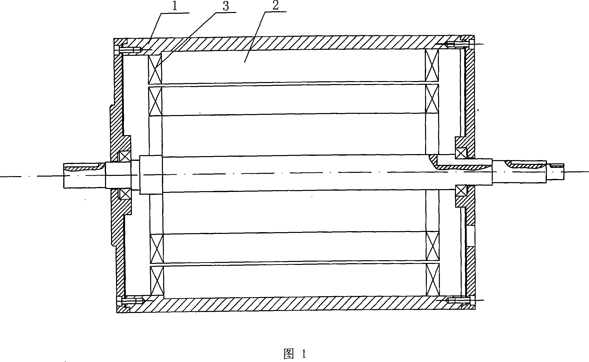
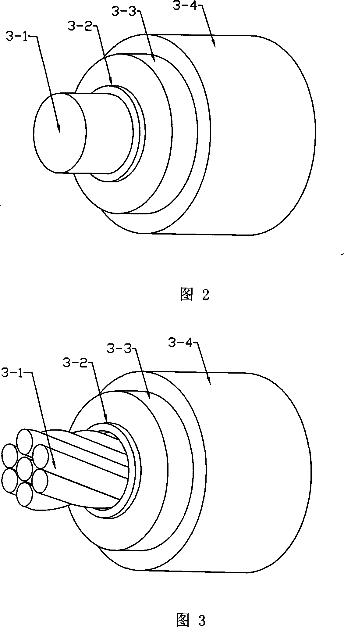
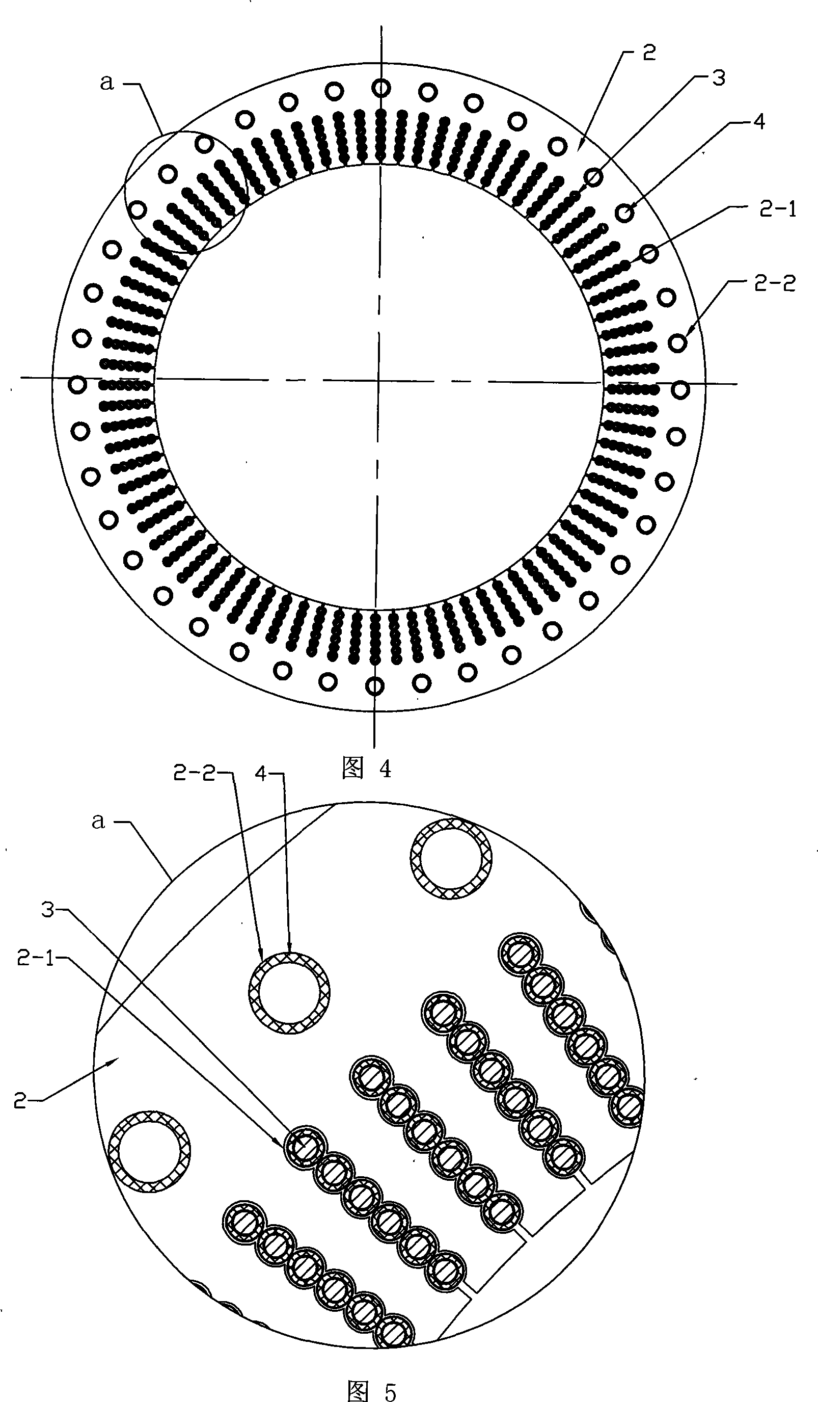
[0021] Specific embodiment 1: This embodiment is described in conjunction with Figures 1 to 11. This embodiment is composed of a stator and a rotor; the stator is composed of a frame 1, an iron core 2, a stator winding 3 and a cooling water pipe 4; the section of the stator winding 3 is Round; stator winding 3 is composed of conductor 3-1, inner semiconducting layer 3-2, insulating layer 3-3, and outer semiconducting layer 3-4 from inside to outside, and conductor 3-1 is a single-strand wire or twisted Multi-strand wires, the outer semiconductor layer 3-4 is connected to the ground potential; there is a wave-shaped winding slot 2-1 along the radial direction of the iron core 2; the stator winding 3 is placed in the wave-shaped winding slot 2-1 of the iron core 2, The stator winding 3 is in clearance fit with the wave-shaped winding slots 2-1; the iron core 2 yoke is evenly opened with at least four circular cooling slots 2-2 in the circumferential direction, and the cooling wat...
specific Embodiment approach 2
[0022] Specific embodiment 2: This embodiment is described in conjunction with Fig. 4 to Fig. 7. The difference between this embodiment and specific embodiment 1 is that the insulating layer 3-3 of the stator winding 3 placed in the wave-shaped winding slot 2-1 is evenly wound on the on the inner semiconductor layer 3-2. Other compositions and connection methods are the same as those in Embodiment 1.
specific Embodiment approach 3
[0023] Specific embodiment 3: This embodiment is described in conjunction with Fig. 8 to Fig. 11. The difference between this embodiment and specific embodiment 1 is that the stator winding 3 placed in the wave-shaped winding slot 2-1 is divided into m groups, m≥2, The thickness of the insulating layers 3 - 3 of the stator winding 3 from the first group to the mth group distributed from the center of the iron core 2 to the circumferential direction increases gradually. Other compositions and connection methods are the same as those in Embodiment 1. The insulation 3-3 of the stator winding 3 in this embodiment adopts step-by-step winding, because the induced voltage of the generator gradually increases from the neutral point of the stator winding to the end of the line, so that the cables produce different voltages along the winding direction. electrical stress. Therefore, thinner insulation is used in the first few turns of the winding, and the thickness of the insulation is ...
PUM
 Abstract
Description
Claims
Application Information