Rackmount system including conversion rail

a rackmount and conversion rail technology, applied in the field of high-configurable rackmount chassis, can solve the problem of not being able to reconfigure the chassis to accept blades of a different height,

Active Publication Date: 2011-11-01
EXTREME NETWORKS INC
View PDF10 Cites 36 Cited by
  • Summary
  • Abstract
  • Description
  • Claims
  • Application Information

AI Technical Summary

Benefits of technology

[0014]Conventional rackmount chassis designs impose fixed size requirements on blades installed into those chassis designs. Specifically, once a conventional rackmount chassis is configured to accept blades of a particular height, reconfiguring that chassis to accept blades of a different height is not possible without removal of the entire chassis from the rackmount system in which it is mounted. By incorporating support plates that run the length of the chassis and removable support rails that are installed onto those supports spans, a rackmount chassis be provided that allows in-situ reconfiguration (i.e., reconfiguration without removal of the chassis from the rack in which is it installed) to accommodate blades of different heights.

Problems solved by technology

Specifically, once a conventional rackmount chassis is configured to accept blades of a particular height, reconfiguring that chassis to accept blades of a different height is not possible without removal of the entire chassis from the rackmount system in which it is mounted.

Method used


Image

  • Rackmount system including conversion rail
  • Rackmount system including conversion rail
  • Rackmount system including conversion rail

Examples


Embodiment Construction

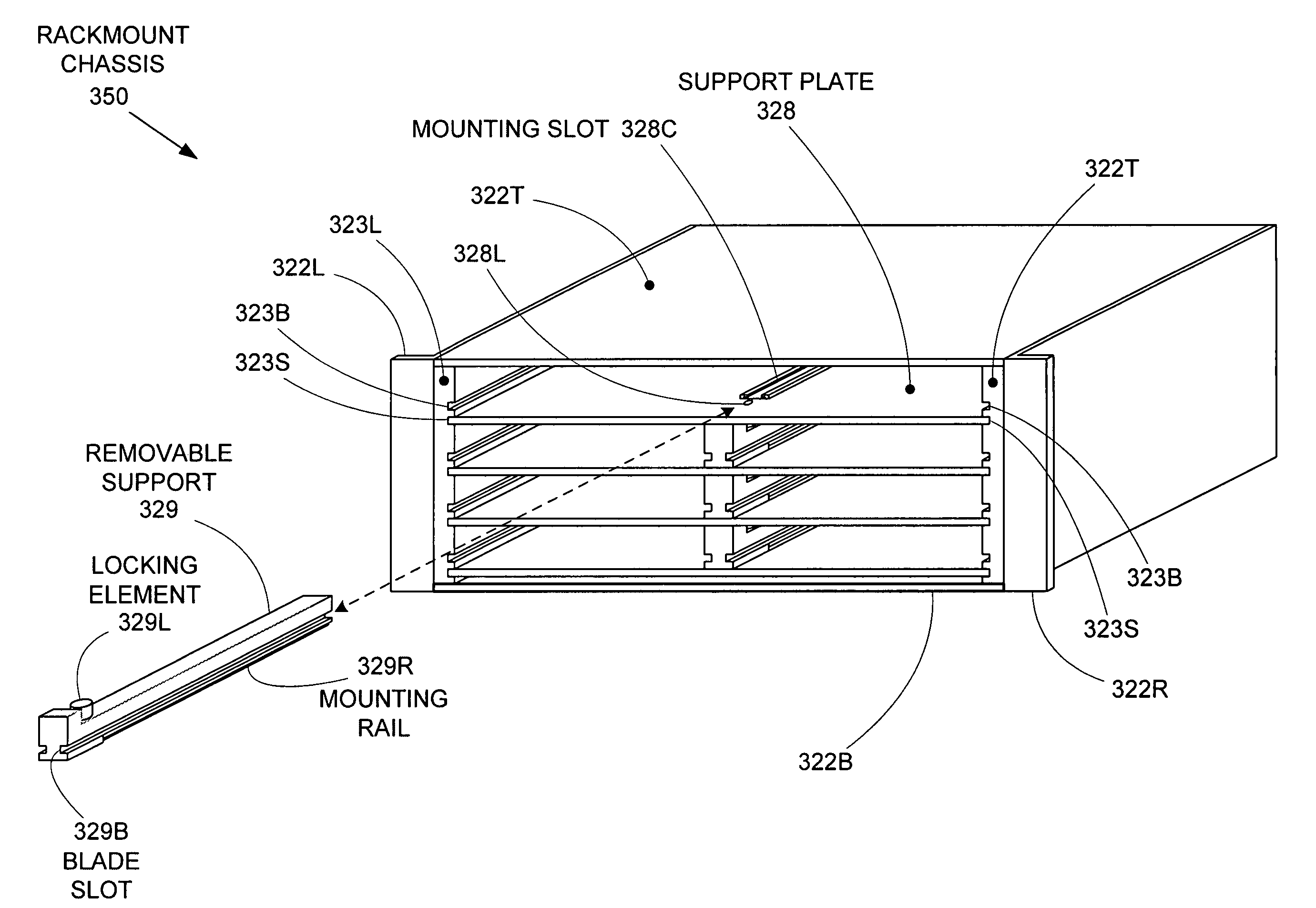
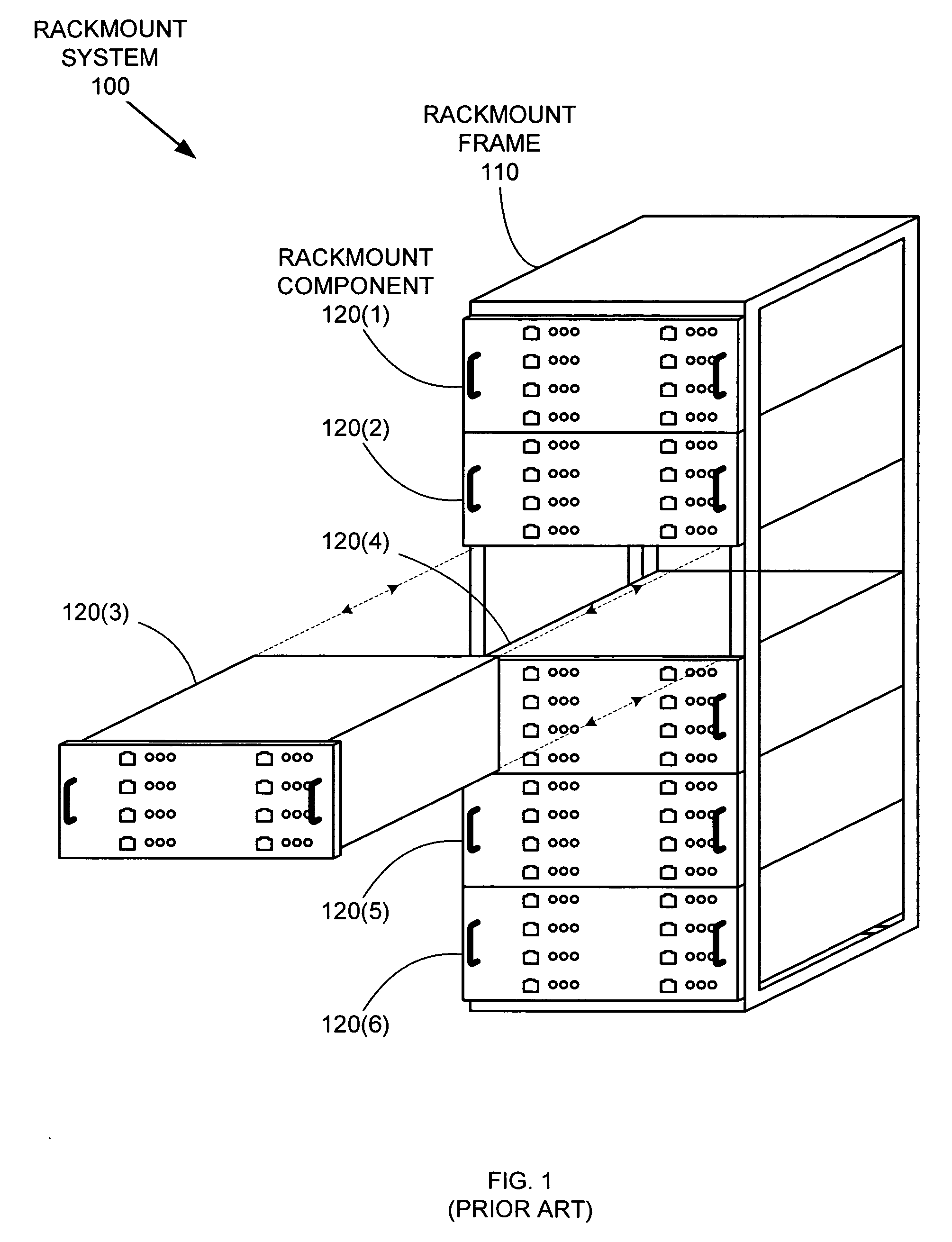
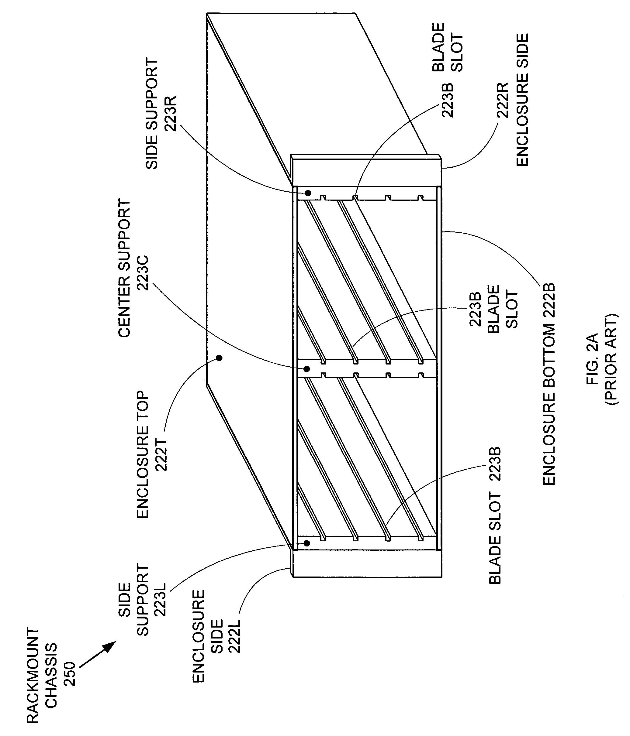
[0026]Conventional rackmount chassis designs impose fixed size requirements on blades installed into those chassis designs. Specifically, once a conventional rackmount chassis is configured to accept blades of a particular height, reconfiguring that chassis to accept blades of a different height is not possible without removal of the entire chassis from the rackmount system in which it is mounted. By incorporating support plates that run the length of the chassis and removable support rails that are installed onto those supports spans, a rackmount chassis be provided that allows in-situ reconfiguration (i.e., reconfiguration without removal of the chassis from the rack in which it is installed) to accommodate blades of different heights.

[0027]FIGS. 3A and 3B show isometric assembly views of a rackmount chassis 350 that incorporates removable support rails to enable in-situ reconfiguration. In FIG. 3A, the initial assembly of rackmount chassis 350 is depicted. Rackmount chassis 350 i...


PUM


Abstract

A rackmount chassis includes removable supports that provide interior support for blades having mounting edge-to-mounting edge dimensions that are less than the full chassis width. The removable supports are mounted on parallel support plates that span the full width of the chassis. Each removable support supports an edge of at least one blade installed into the rackmount chassis. The locations of the removable supports on the parallel support plates determine the blade form factors (mounting edge-to-mounting edge dimensions) that the rackmount chassis can accept. Because the removable supports can be individually removed / installed, the configuration of the resulting rackmount component can be changed without physically removing the rackmount component from the rack in which it is mounted.

Description

BACKGROUND OF THE INVENTION[0001]1. Field of the Invention[0002]The invention relates to an electronics enclosure, and in particular, to a highly configurable rackmount chassis.[0003]2. Related Art[0004]Large electronic installations are often implemented using rackmount architecture to provide maximum space efficiency and large-scale modularity. Rackmount systems typically follow the Electronics Industry Alliance (EIA) standard EIA-310-D that specifies an overall rackmount system width of 19 inches. Rackmount components must therefore be designed to fit within the specified system limits.[0005]FIG. 1 shows an exemplary rackmount system 100 that includes a rack 110 populated by rackmount components 120. Rack 110 is simply a metal framework that defines an installation space for rackmount components 120. Rackmount components 120 (e.g., servers, routers, switches, and other electronic devices) are installed into rack 110, thereby providing a modular, standardized electronics system in...

Claims


Application Information

Patent Timeline
Patent Type & Authority Patents(United States)
IPC IPC(8): A47F7/00
CPCH05K7/1418H05K7/1425
Inventor HENDRIX, ALVIN F.RIVARD, DANIEL L.NGUYEN, RICK-NGHIA T.
Owner EXTREME NETWORKS INC
Why Eureka
Try Eureka