Relay connector

a technology of relay connectors and connectors, applied in the direction of coupling contact members, fixed connections, coupling device connections, etc., can solve problems such as inability to stably transmit signals, and achieve the effect of stable signal transmission characteristics and constant connection resistance between leads

Active Publication Date: 2011-12-20
MOLEX INC
View PDF15 Cites 6 Cited by
  • Summary
  • Abstract
  • Description
  • Claims
  • Application Information

AI Technical Summary

Benefits of technology

[0008]The present invention has an object thereof to solve the above-mentioned problems, by providing a relay connector for flat cables having conductive leads exposed in a bare condition and mutually stacked so as to come face to face with each other. The connector includes terminals provided with pressing projections, a first arm portion and a second arm portion, each extending in a direction along which insertion and withdrawal direction of the flat cables are performed, and a connecting portion that connects the first arm portion and the second arm portion. Due to the described configuration, an attitude change of an actuator from a first position to a second position changes an angle of the first or second arm portion so that the pressing projection of the first arm portion or the pressing projection of the second arm portion is urged to displace toward a line of direction in which the insertion is performed. This results in the conductive leads of the respective flat cables forming together a contact point at a position corresponding to the pressing projections, and that these conductive leads are spaced apart when they come apart from the contact point in the insertion direction. Consequently, the connecting resistance between both conductive leads is constant, enabling acquirement of stable transmission characteristics of signals.
[0013]In accordance with the present invention, the relay connector is adapted for flat cable insertion with conductive leads exposed in a bare condition and stacked to come face to face with each other, has pressing projections, and a first and second arm portion, each extending along the insertion direction of the flat cables, and terminals each for connecting the first arm portion and the second arm portion. Movement of the actuator from the first position to the second position changes the angle of the first or second arm portion so that the pressing projections of the first or second arm portions are displaced in the insertion direction. The leads of the respective flat cables are formed at contact points at the position corresponding to the pressing projections, and that these leads are spaced apart in the insertion direction from the contact point. Consequently, the connection resistance between the leads is constant, permitting stable transmission characteristics of signals.

Problems solved by technology

Thus, the change in the electric connecting resistance between both conductive leads 304 and 307 could cause unstable transmission characteristics, resulting in becoming unable to stably transmit signals.

Method used


Image

  • Relay connector
  • Relay connector
  • Relay connector

Examples


Embodiment Construction

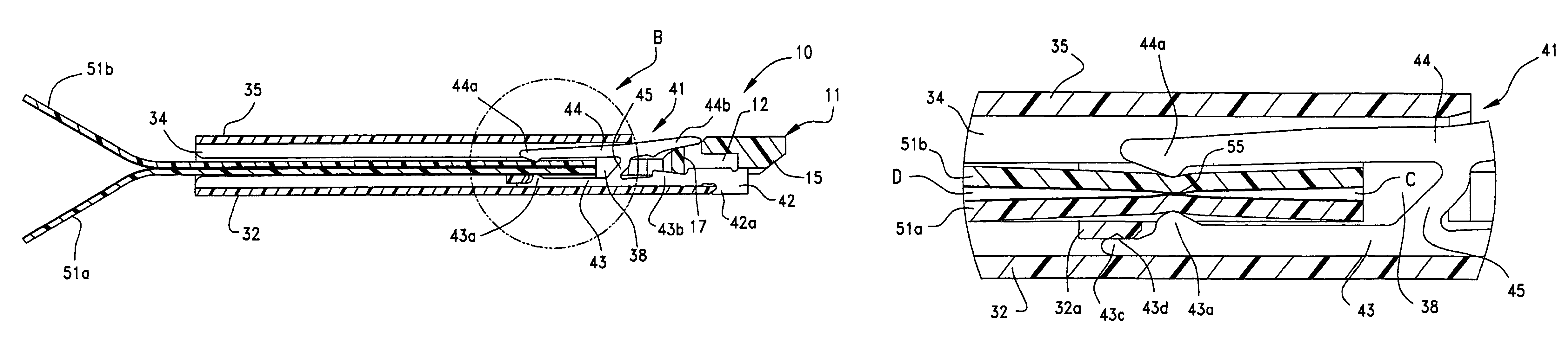
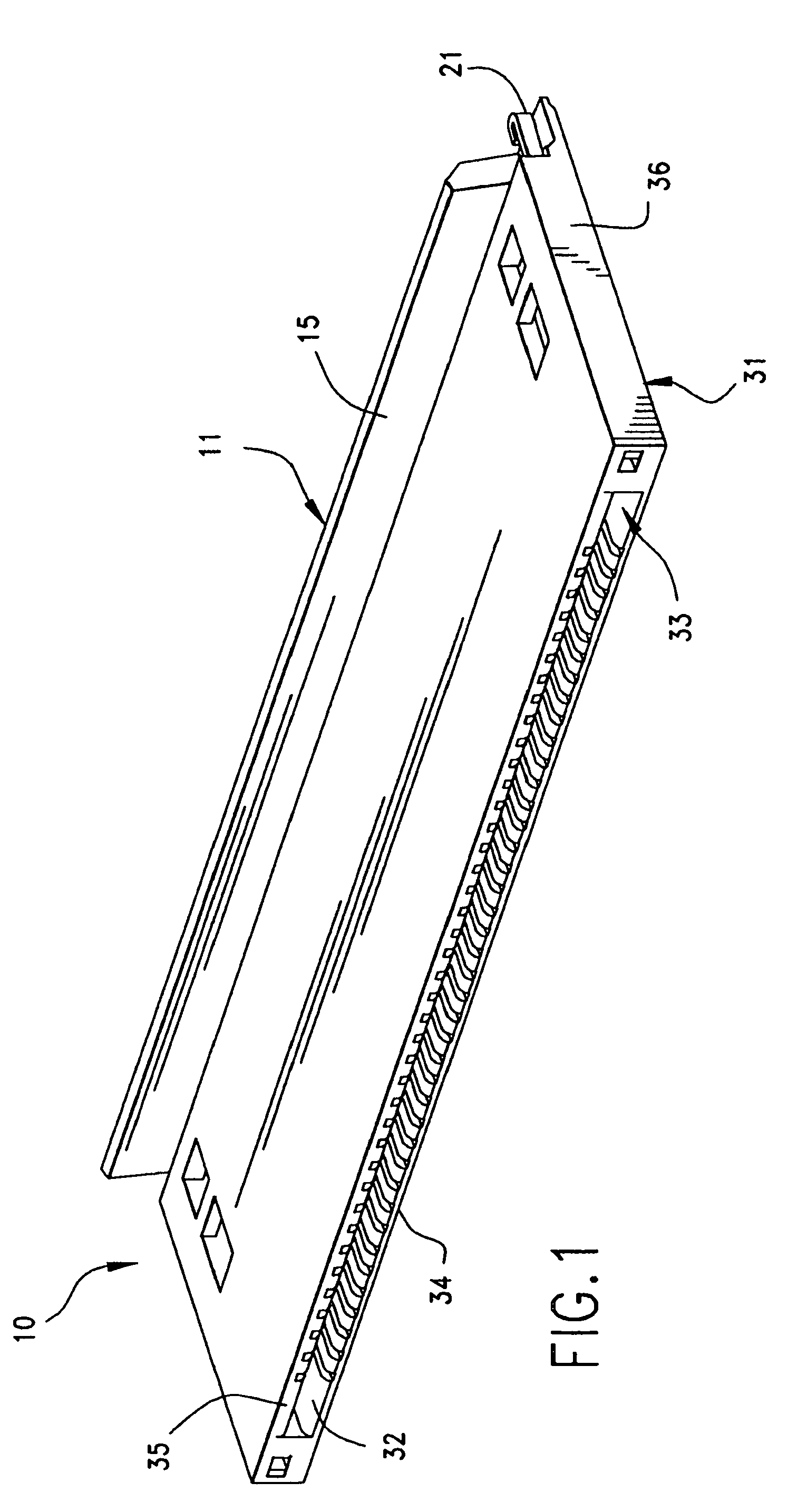
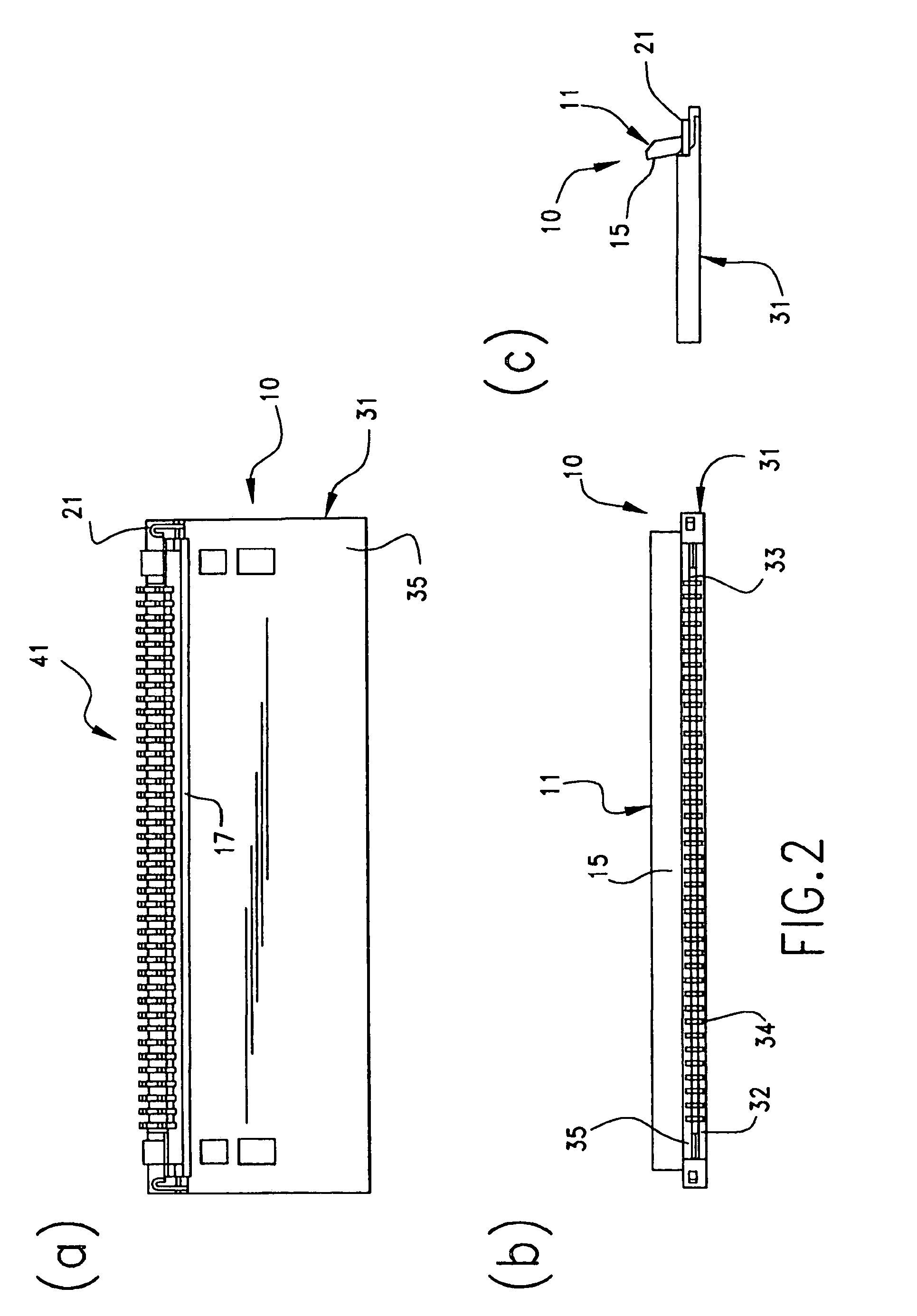
[0021]In these drawing figures, the reference numeral 10 designates a connector which is a relay connector according to the present embodiment, which is used to provide connection between a first flat cable 51a and a second flat cable 51b that are called flexible printed circuits, flexible flat cables, or the like. In the present embodiment, the first flat cable 51a and the second flat cable 51b are connected to each other by inserting them into the connector 10, with their respective ends stacked upon each other as shown in FIG. 3. The first and second flat cables 51a and 51b are stacked so that their surfaces on which conductive leads are formed, come face to face with each other. The cables 51a and 51b are of the same construction, and accordingly hereinafter, they will be commonly referred to as “flat cables 51”. Although the flat cables 51 are flat flexible cables called such as FPC, FFC, or the like, they may be of any type of flat cable provided with conductive leads.

[0022]Th...


PUM


Abstract

A flat flexible cable connector (10) has a housing (31) with an insertion opening (33) in its front face. Two lengths of flexible cable (51a, 51b) are placed end to end and are inserted into the opening. The connector has terminals (41) with top and bottom opposing contact portions (43a, 44a) which are aligned with the exposed conductive leads on the two lengths of flexible cables. A moveable actuator (11) applies pressure to the terminal contact portions to effect a reliable connection between the flexible cables.

Description

RELATED CROSS-REFERENCES[0001]The Present Disclosure is a U.S. National Phase Application of Patent Cooperation Treaty (PCT) Patent Application No. PCT / US2007 / 0007891, entitled “Relay Connector,” filed with the United States Patent and Trademark Office, as Receiving Office for the PCT on 29 Mar. 2007. The PCT Application claims priority to prior-filed Japanese Patent Application No. 2006-089873, entitled “Relay Connector,” filed on 29 Mar. 2006 with the Japanese Patent Office. The contents of each of the aforementioned Patent Applications are fully incorporated in their entireties herein.BACKGROUND OF THE INVENTION[0002]The present invention relates to a relay connector for not exclusively but preferably providing a connection between flat cables.[0003]Conventionally, relay connectors provide electrical connection between flat cables, each having flexibility and being often referred to as a flexible printed circuit (FPC) or a flexible flat cable (FFC). One such connector is describe...

Claims


Application Information

Patent Timeline
Patent Type & Authority Patents(United States)
IPC IPC(8): H01R13/15
CPCH01R12/61H01R12/79H01R12/78H01R31/06
Inventor SUZUKI, TERUHITOHIRATA, HIDEYUKIMURAKAMI, KOJILI, CONG
Owner MOLEX INC
Why Eureka
Try Eureka