End effector for use with a surgical cutting and stapling instrument

a technology for surgical cutting and stapling instruments and end effectors, which is applied in the field of endoscopic surgical instruments, can solve problems such as complicated tasks

Active Publication Date: 2011-12-27
CILAG GMBH INT
View PDF933 Cites 1585 Cited by
  • Summary
  • Abstract
  • Description
  • Claims
  • Application Information

AI Technical Summary

Problems solved by technology

This task may be complicated due to the location of the tissue and / or the position of the end effector within the body cavity.

Method used


Image

  • End effector for use with a surgical cutting and stapling instrument
  • End effector for use with a surgical cutting and stapling instrument
  • End effector for use with a surgical cutting and stapling instrument

Examples


Embodiment Construction

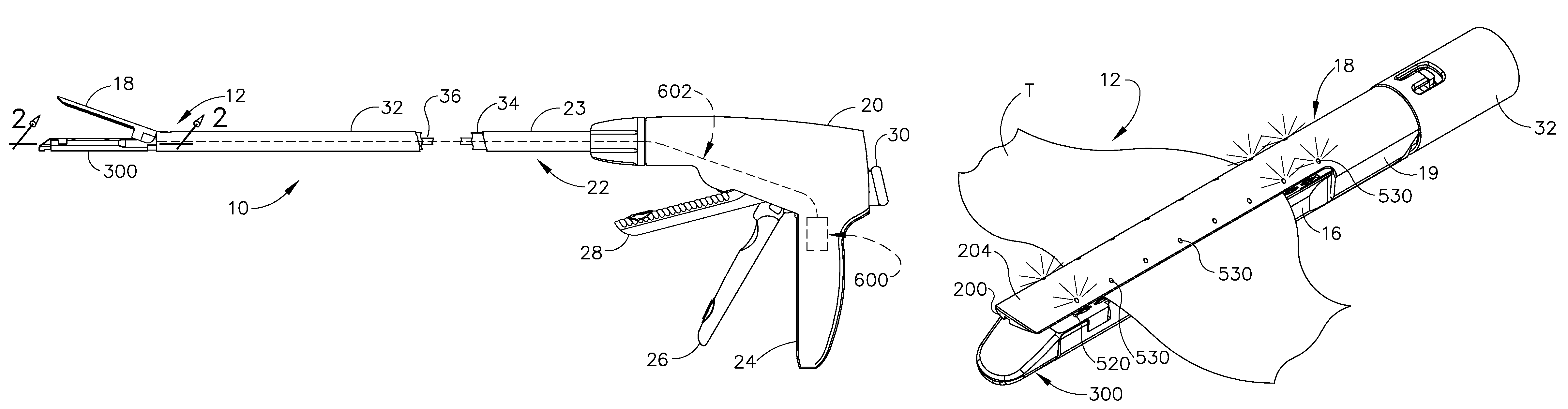
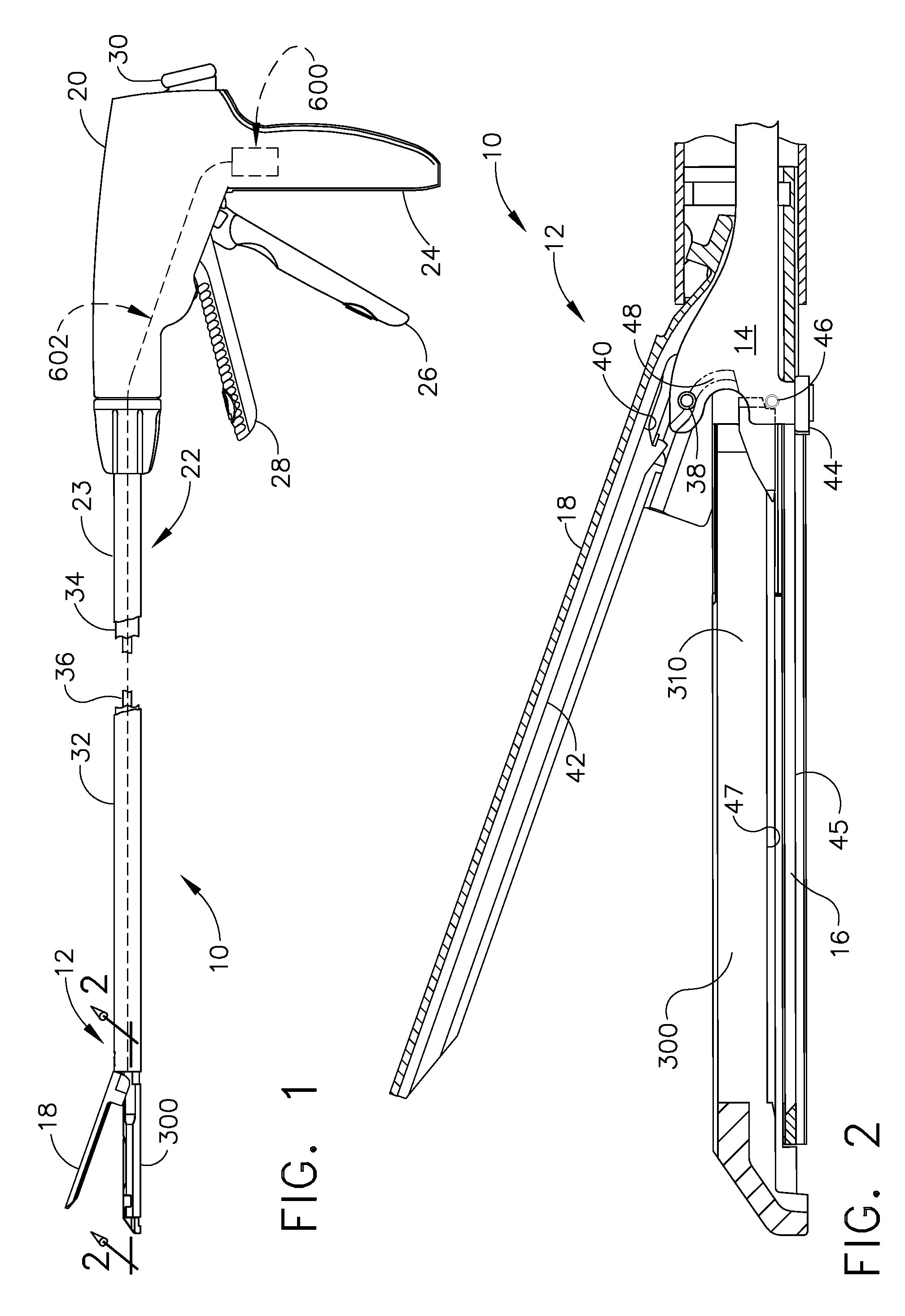
[0029]Turning to the Drawings, wherein like numerals denote like components throughout the several views, FIGS. 1 and 2 depict one embodiment of a surgical stapling and severing instrument 10 that is capable of practicing the unique benefits of the present invention. As the present Detailed Description proceeds, the reader will appreciate, however, that the unique and novel aspects of the present invention may be advantageously employed in connection with a variety of other staplers, stapler instruments and even tissue grasping instruments without departing from the spirit and scope of the present invention. Accordingly, the scope of protection afforded to the various embodiments of the present invention should not be limited to use only with the specific type of surgical cutting and stapling instruments described herein.

[0030]FIGS. 1 and 2, illustrate one form of a surgical cutting and stapling instrument, generally designated as 10 that may be effectively employed in connection wi...


PUM

PropertyMeasurementUnit
angleaaaaaaaaaa
electrical energyaaaaaaaaaa
colorsaaaaaaaaaa

Abstract

An end effector for a surgical cutting and stapling instrument. In various embodiments, the end effector may include an elongate channel that is configured to support a staple cartridge therein and which is also operably coupled to a surgical cutting and stapling instrument. An anvil may be movably supported relative to the elongate channel for selective movement between an open position and a closed position wherein tissue is clamped between the anvil and a staple cartridge supported within the elongate channel in response to a closing motion applied thereto from the surgical cutting and stapling instrument. At least one light source may be provided on at least one of the staple cartridge and the elongate channel. The light sources may interface with the anvil to provide a visual indication viewable through a portion of the anvil to indicate a position of tissue clamped between the anvil and the staple cartridge.

Description

FIELD OF THE INVENTION[0001]The present invention relates in general to endoscopic surgical instruments that are capable of manipulating tissue and applying lines of staples to tissue while cutting the tissue between those staple lines and, more particularly, to improvements relating to end effectors for such instruments.BACKGROUND OF THE INVENTION[0002]Surgical staplers have been used in the prior art to simultaneously make a longitudinal incision in tissue and apply lines of staples on opposing sides of the incision. Such instruments commonly include a pair of cooperating jaw members that, if the instrument is intended for endoscopic or laparoscopic applications, are capable of passing through a cannula passageway. One of the jaw members is configured to receive a staple cartridge equipped with laterally spaced rows of staples. The other jaw member commonly comprises an anvil that has staple-forming pockets formed therein that are aligned with the rows of staples in the cartridge....

Claims


Application Information

Patent Timeline
Patent Type & Authority Patents(United States)
IPC IPC(8): A61B17/68
CPCA61B17/07207A61B19/5202A61B2019/4857A61B2017/07271A61B2017/07214A61B90/30A61B2090/0811
Inventor SHELTON, IV, FREDERICK E.SCHWEMBERGER, RICHARD F.YATES, DAVID C.SMITH, RICHARD C.
Owner CILAG GMBH INT
Why Eureka
Try Eureka