Medical tube assemblies

a technology of medical tubes and tubes, applied in the field of medical tube assemblies, can solve the problems of the tip of the catheter or device to catch on the inturned lip at the patient end of the tube, the patient's periodic removal and replacement of the tube is relatively traumatic and uncomfortable, and the inner cannula is relatively small

Active Publication Date: 2012-01-31
SMITHS MEDICAL INT
View PDF20 Cites 17 Cited by
  • Summary
  • Abstract
  • Description
  • Claims
  • Application Information

AI Technical Summary

Problems solved by technology

Periodic removal and replacement of the tube is relatively traumatic and uncomfortable for the patient, and must be carried out by surgical staff.
There are, however, problems with inner cannulae.
One problem, however, with this arrangement is that when the inner cannula has been removed and a suction catheter or other elongate device is inserted through the outer tube to extend beyond the patient end of the outer tube, there is a tendency for the tip of the catheter or device to catch on the inturned lip at the patient end of the tube.

Method used


Image

  • Medical tube assemblies
  • Medical tube assemblies
  • Medical tube assemblies

Examples


Embodiment Construction

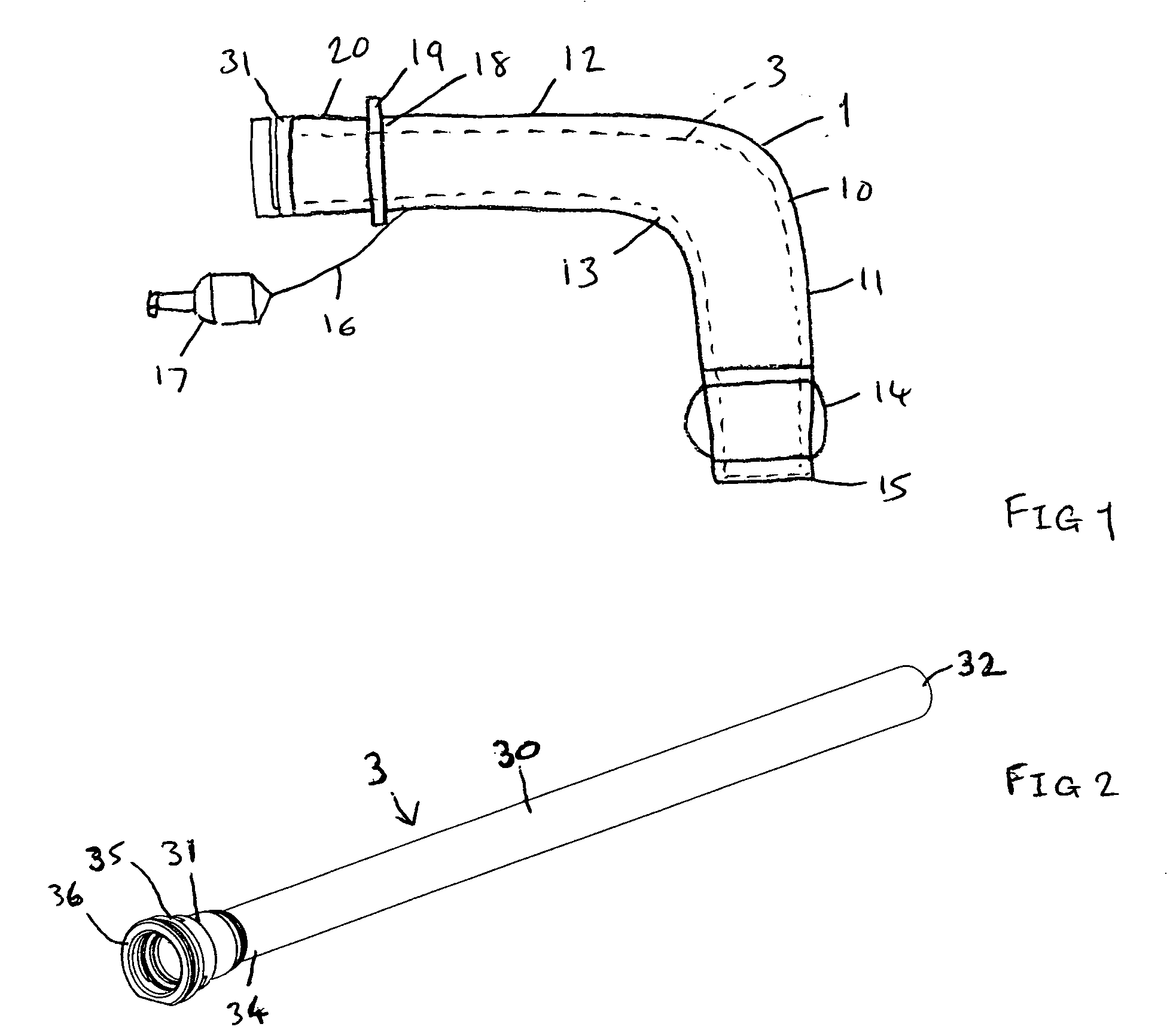
[0019]With reference first to FIG. 1, the tracheostomy tube assembly comprises an outer tube 1 and an inner tube or cannula 3, which is removable from the outer tube so that it can be periodically replaced in the usual way.

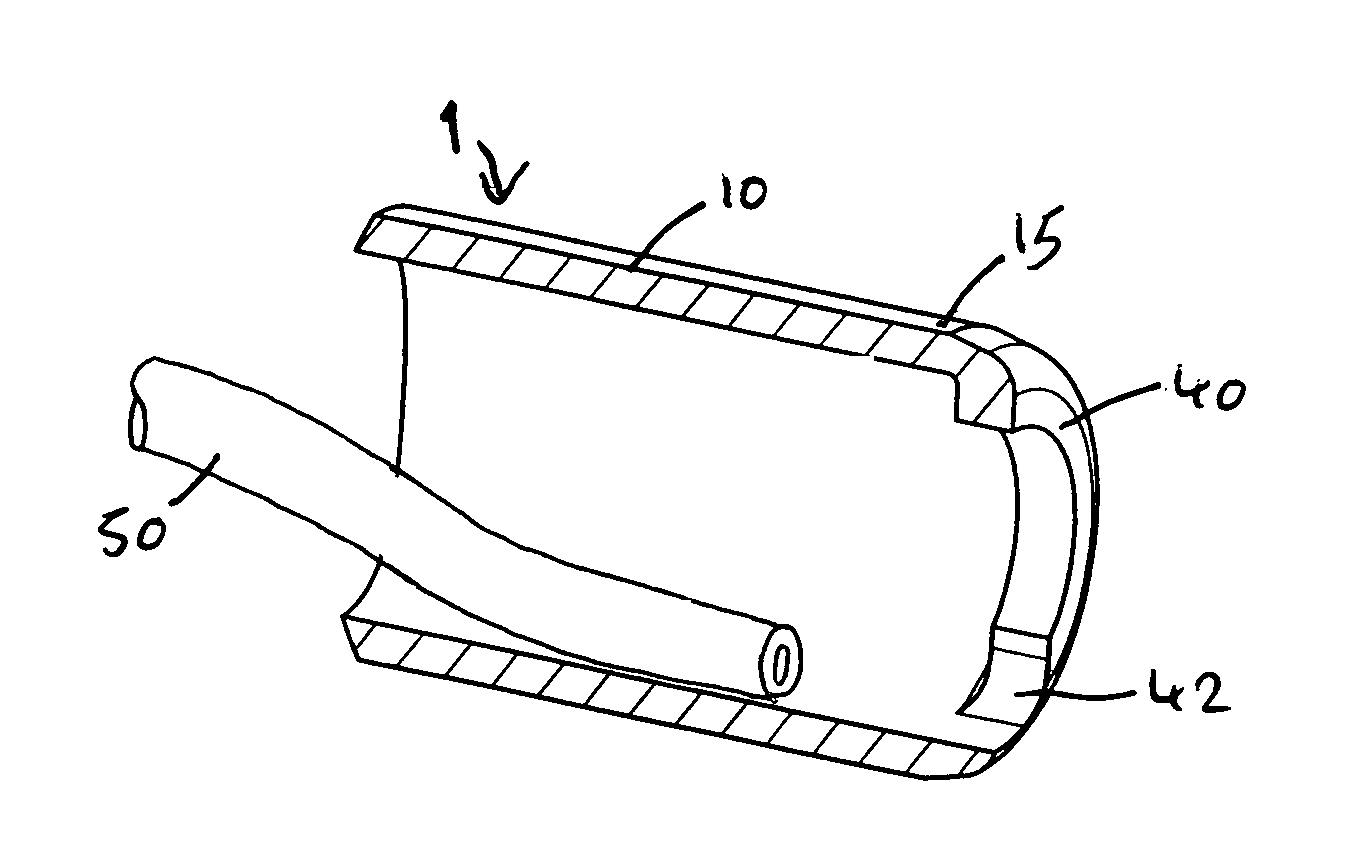
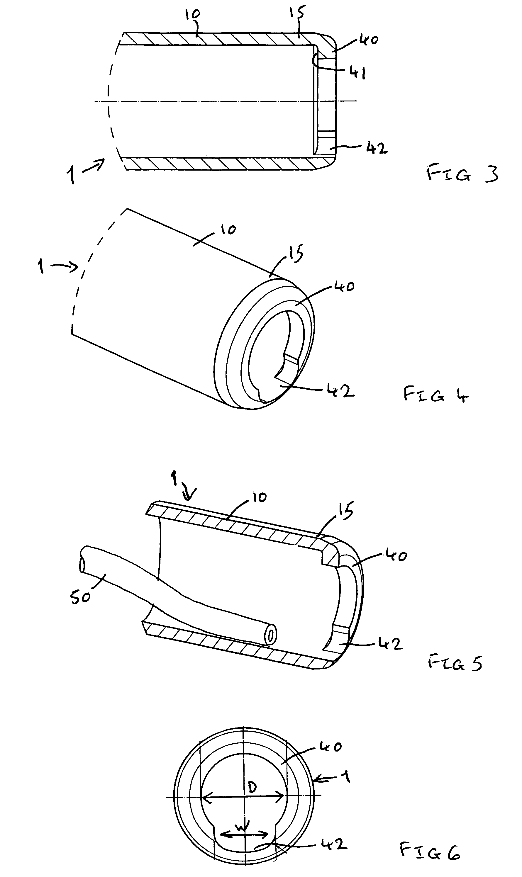
[0020]The outer tube 1 has a shaft 10 with straight forward or patient end section 11 and rear or machine end section 12 joined by a right-angle bend section 13. Alternatively, the outer tube could be smoothly curved along its entire length. In another embodiment the tube could have a natural straight shape and be highly flexible so that it could be bent during use to the shape of the anatomy. Such a flexible tube might be reinforced, such as by a helical wire reinforcement. The tube 1 typically has an external diameter of about 11.3 mm and an internal diameter of about 9.3 mm. A sealing cuff 14 embraces the shaft 10 close to its patient end 15; this can be inflated for sealing, or deflated for insertion and removal, via an inflation line 16 and a combined inflati...


PUM


Abstract

A tracheostomy assembly has an outer tube and an inner cannula, the outer tube having a lip at its patient end to limit insertion of the inner cannula. The lip is formed with a recess or gap on the outside of the curve of the tube. This enables a suction catheter or similar device to be slid along the tube, after removal of the inner cannula, without the risk of catching on the lip.

Description

BACKGROUND OF THE INVENTION[0001]This invention relates to medical tube assemblies.[0002]Tracheostomy tubes are inserted through a surgically-made opening in the throat so that one end of the tube locates in the trachea and the other end projects externally. Ventilation gas can then be supplied to the patient's airways via the tube or the patient can breath normally through the tube.[0003]Tracheostomy tubes are often used where prolonged ventilation is required. In use, however, the inside of the tube becomes coated with secretions, which can reduce the flow of gas along the tube and provide a site for bacteria to multiply. Periodic removal and replacement of the tube is relatively traumatic and uncomfortable for the patient, and must be carried out by surgical staff. It is, therefore, preferable to clean the tube, either by using a suction catheter inserted along the bore of the tube or, preferably, by using an inner cannula. Where an inner cannula is used, this is configured to fo...

Claims


Application Information

Patent Timeline
Patent Type & Authority Patents(United States)
IPC IPC(8): A61M16/00
CPCA61M16/0463A61M16/0465A61M16/0427A61M16/0434
Inventor CHEUNG, JAZMINE MINGLAI
Owner SMITHS MEDICAL INT
Why Eureka
Try Eureka