MEMS sensor with movable z-axis sensing element

a sensing element and sensor technology, applied in the field of sensing elements for mems sensors, can solve problems such as undesirable affecting the reliability of this measuremen

Active Publication Date: 2012-04-03
ANALOG DEVICES INC
View PDF5 Cites 38 Cited by
  • Summary
  • Abstract
  • Description
  • Claims
  • Application Information

AI Technical Summary

Problems solved by technology

However, parasitic capacitance between the electrode and the substrate may undesirably impact the reliability of this measurement.

Method used


Image

  • MEMS sensor with movable z-axis sensing element
  • MEMS sensor with movable z-axis sensing element
  • MEMS sensor with movable z-axis sensing element

Examples


Embodiment Construction

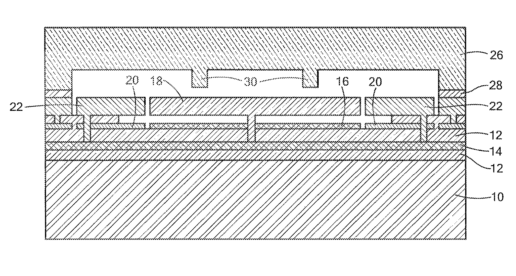
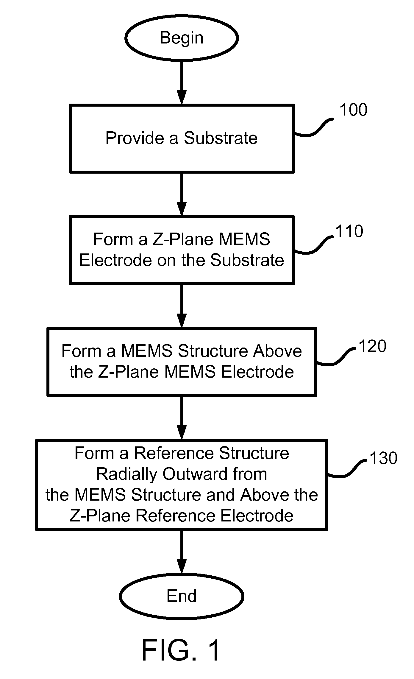
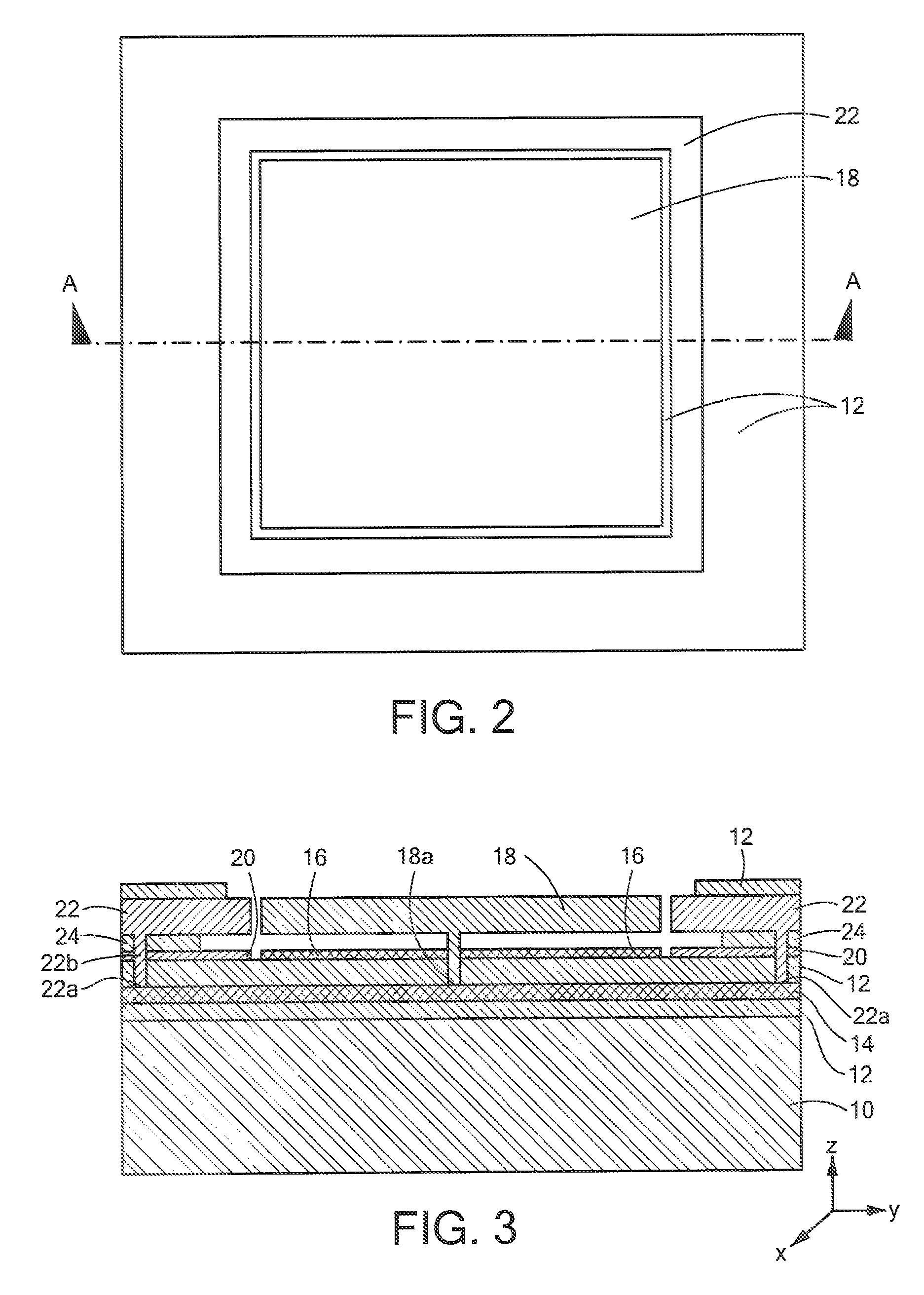
[0015]Various embodiments of the present invention provide a movable sensing element for measuring z-axis movement in a MEMS sensor. The movable sensing element is formed from a MEMS structure having a movable mass and an external reference structure located radially outward from the MEMS structure. In some embodiments, the reference structure may substantially surround the MEMS structure and be coplanar with it. The external reference structure is physically separate from, but electrically coupled to, the movable mass of the MEMS structure. This configuration, in conjunction with a z-plane MEMS electrode underneath the MEMS structure, allows the movable sensing element to sense changes in capacitance between the z-plane MEMS electrode and the sensing element as the movable mass moves in the z-axis. Details of illustrative embodiments are discussed below.

[0016]As known by those skilled in the art, MEMS structures are commonly made by a sequence of thin film depositions and etches pe...


PUM


Abstract

A MEMS sensor includes a substrate and a MEMS structure coupled to the substrate. The MEMS structure has a mass movable with respect to the substrate. The MEMS sensor also includes a reference structure positioned radially outward from the MEMS structure. The reference structure is used to provide a reference to offset any environmental changes that may affect the MEMS sensor in order to increase the accuracy of its measurement.

Description

FIELD OF THE INVENTION[0001]The invention generally relates to sensing elements for MEMS sensors and, more particularly, the invention relates to a movable sensing element for measuring z-axis movement in MEMS sensors.BACKGROUND OF THE INVENTION[0002]Sensors employing microelectromechanical systems (MEMS) devices are increasingly used in different applications to detect the movement of an underlying object or the presence of a substance or condition due to their relatively small size and their capability to detect relatively small amounts or changes in the measured item. MEMS devices typically employ a movable, inertial mass or flexible membrane formed with one or more fixed, non-moving structures or fingers. For example, in a MEMS accelerometer, the inertial mass may be suspended in a plane above a substrate and movable with respect to the substrate. The movable structure and the fixed structures form a capacitor having a capacitance that changes when the movable structure moves re...

Claims


Application Information

Patent Timeline
Patent Type & Authority Patents(United States)
IPC IPC(8): G01P15/125
CPCG01P15/0802G01P21/00G01P15/18G01P15/125
Inventor ZHANG, XINJUDY, MICHAEL W.
Owner ANALOG DEVICES INC
Why Eureka
Try Eureka