Radio frequency (RF) transition design for a phased array antenna system utilizing a beam forming network

a phased array and beam forming technology, applied in the direction of resonant antennas, radiating element structural forms, antenna supports/mountings, etc., can solve the problems of limiting the choice of suppliers for the system, affecting the cost and schedule of production of the antenna, and design challenges, so as to achieve the effect of reducing the loss of r

Active Publication Date: 2012-04-10
THE BOEING CO
View PDF19 Cites 17 Cited by
  • Summary
  • Abstract
  • Description
  • Claims
  • Application Information

AI Technical Summary

Benefits of technology

[0008]Embodiments of an RF transition system are disclosed. According to one or more embodiments, the RF transition system comprises a stripline trace section with openings in ground planes, forming a quarter-wavelength resonator. The RF transition system further includes an electromagnetic mechanism to couple the RF energy from the stripline trace section to a connector. The RF signal energy is transferred from inside a beam forming network printed wiring board to an antenna back plane with minimal RF losses.
[0010]According to another embodiment, a phased array antenna system includes a printed wiring board formed in rhombic shape that accommodates requirements for low observability, a beam forming network located within the printed wiring board, wherein the beam forming network is located over substantially the entire printed wiring board, an RF transition system comprising a stripline trace section with openings in ground planes and forms a quarter wavelength resonator and an electromagnetic mechanism to couple the RF energy from the stripline trace section to a connector, wherein the RF signal energy is transferred from inside the printed wiring board to a back side of a phased array antenna system with minimal RF losses and connectors located on the backside of the printed wiring board that allows for expansion of the system.
[0011]According to yet another embodiment, a method for transferring RF signal energy includes forming a quarter wavelength resonator, coupling the RF signal energy from a stripline trace section to a connector, wherein the RF signal energy is transferred from inside a beam forming network printed wiring board to an a back side of a phased array antenna system with minimal RF losses.

Problems solved by technology

There are design challenges when utilizing a phased array antenna system.
Conventional designs had tighter tolerances in the feature alignments of the RF transition, which limits the choice of suppliers for the systems and impacts the cost and schedule for producing the antennas as well.

Method used


Image

  • Radio frequency (RF) transition design for a phased array antenna system utilizing a beam forming network
  • Radio frequency (RF) transition design for a phased array antenna system utilizing a beam forming network
  • Radio frequency (RF) transition design for a phased array antenna system utilizing a beam forming network

Examples


Embodiment Construction

[0029]The present embodiment relates generally to beam forming networks and more particularly to phased array antennas utilizing such networks. The following description is presented to enable one of ordinary skill in the art to make and use the embodiment and is provided in the context of a patent application and its requirements. Various modifications to the embodiments and the generic principles and features described herein will be readily apparent to those skilled in the art. Thus, the present embodiment is not intended to be limited to the embodiments shown, but is to be accorded the widest scope consistent with the principles and features described herein.

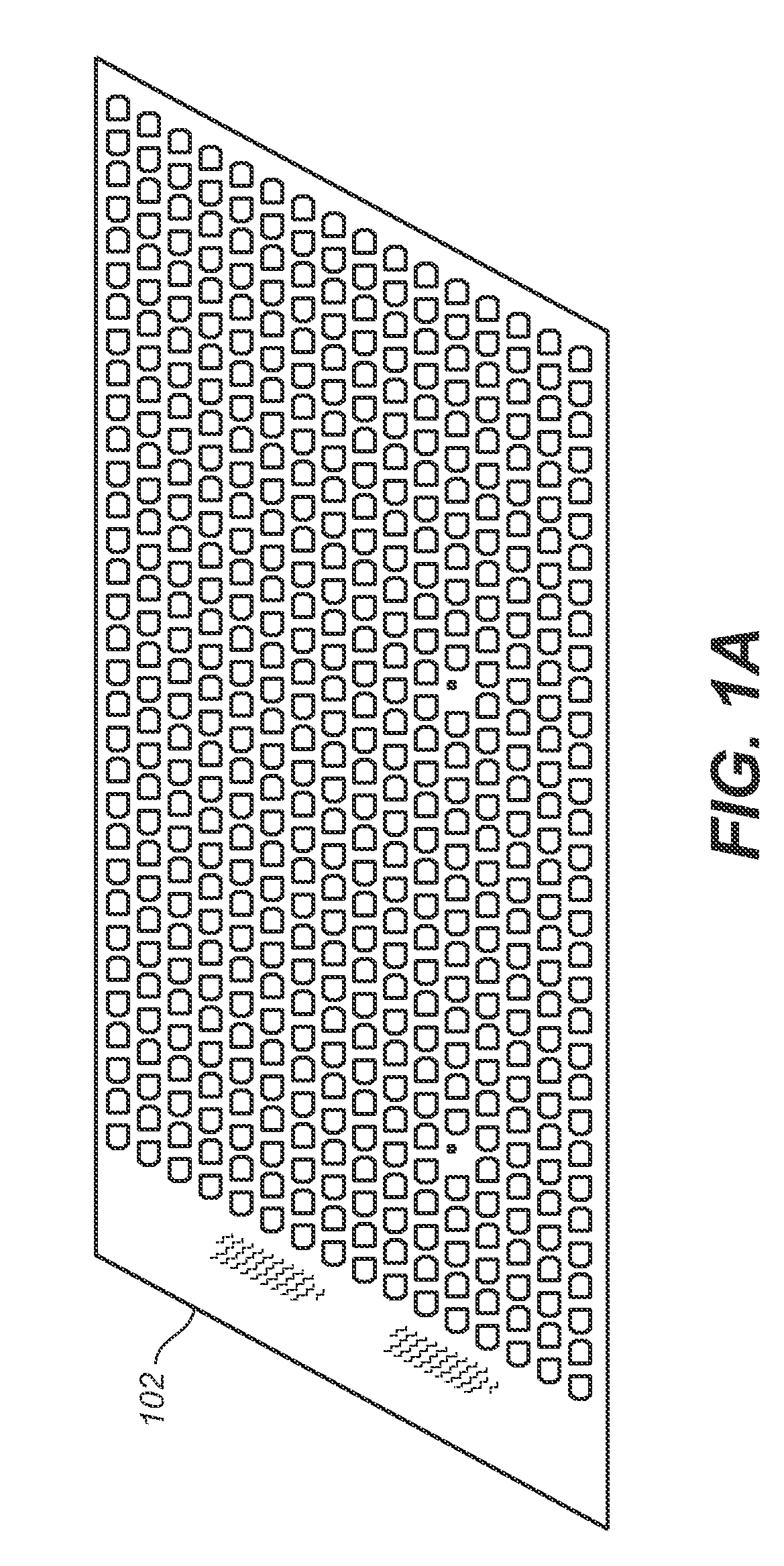
[0030]Every phased array antenna system includes a beam forming network to coherently combine the signals from all of its many elements. It is this signal combining ability that forms the electromagnetic beam. FIG. 1A shows a beam forming distribution board 10 for a conventional phased array antenna system which has the rect...


PUM


Abstract

In accordance with an embodiment, a radio frequency transition system includes a stripline trace section with openings in ground planes and forms a quarter wavelength resonator and an electromagnetic mechanism to couple the RF energy from the stripline trace section to a connector, wherein the RF signal energy is transferred from inside a beam forming network printed wiring board to an a back side of a phased array antenna system with minimal RF losses. An RF transition system is disclosed. The RF transition system comprises a stripline trace section with openings in ground planes and forms a quarter-wavelength resonator. The RF transition system further includes an electromagnetic mechanism to couple the RF energy from the stripline trace section to a connector. The RF signal energy is transferred from inside a beam forming network printed wiring board to an a back side of a phased array antenna system with minimal RF losses.

Description

CROSS-REFERENCE TO RELATED APPLICATIONS[0001]This application is related to co-pending patent application filed concurrently on even-date herewith, entitled, “A Phased Array Antenna System Utilizing A Beam Forming Network” as Ser. No. 11 / 767,129, all of which is incorporated herein by reference.FIELD OF THE INVENTION[0002]The present embodiments relate generally to beam forming networks and more particularly to phased array antennas utilizing such networks.BACKGROUND[0003]Active phased array antenna systems are capable of forming one or more antenna beams of electromagnetic energy and electronically steering the beams to targets, with no mechanical moving parts involved. A phased array antenna system has many advantages over other types of mechanical antennas, such as dishes, in terms of beam steering agility and speed, low profiles, low observability, and low maintenance.[0004]A beam forming network is a major and critical part of a phased array antenna system. The beam forming net...

Claims


Application Information

Patent Timeline
Patent Type & Authority Patents(United States)
IPC IPC(8): H01Q1/50
CPCH01Q9/0414H01Q21/065
Inventor MCKINLEY, CHRIS D.CHEN, MINGO'CONNELL, JOHN B.
Owner THE BOEING CO
Why Eureka
Try Eureka