Check patentability & draft patents in minutes with Patsnap Eureka AI!

Compound electromachining

a technology of electro-mechanical and compounding, applied in the field of machining, can solve the problems of increasing the difficulty of machining metal during the manufacturing process, affecting the rate of production and cost of the final engine, and substantial expenditure of resources and tim

Active Publication Date: 2012-04-24
GENERAL ELECTRIC CO
View PDF13 Cites 5 Cited by
  • Summary
  • Abstract
  • Description
  • Claims
  • Application Information

AI Technical Summary

Problems solved by technology

Various manufacturing processes are available for efficiently manufacturing compressor and turbine blades, yet nevertheless the multitude of such blades requires a substantial expenditure of resources and time, which affect the rate of production and cost of the final engines.
However, these preforms are made of superalloy metals, such as nickel based superalloys, which have enhanced strength for use in the gas turbine engine, which enhanced strength increases the difficulty of machining metal during the manufacturing process.
However, the machined airfoil has its final dimensions and surface finish, and simple fixturing thereof could lead to unacceptable damage to the airfoil, and therefore the airfoil is protected by encapsulation which encapsulation may then be simply fixtured in the grinding machine.
The separate processes typically required in machining the preforms to the finally configured rotor blades typically require multiple machines and multiple operators, which also correspondingly increases the attendant costs.
And, the large batch processing of the preforms renders uneconomical the processing of fewer blades when required for lower production requirements.

Method used


Image

  • Compound electromachining
  • Compound electromachining
  • Compound electromachining

Examples


Embodiment Construction

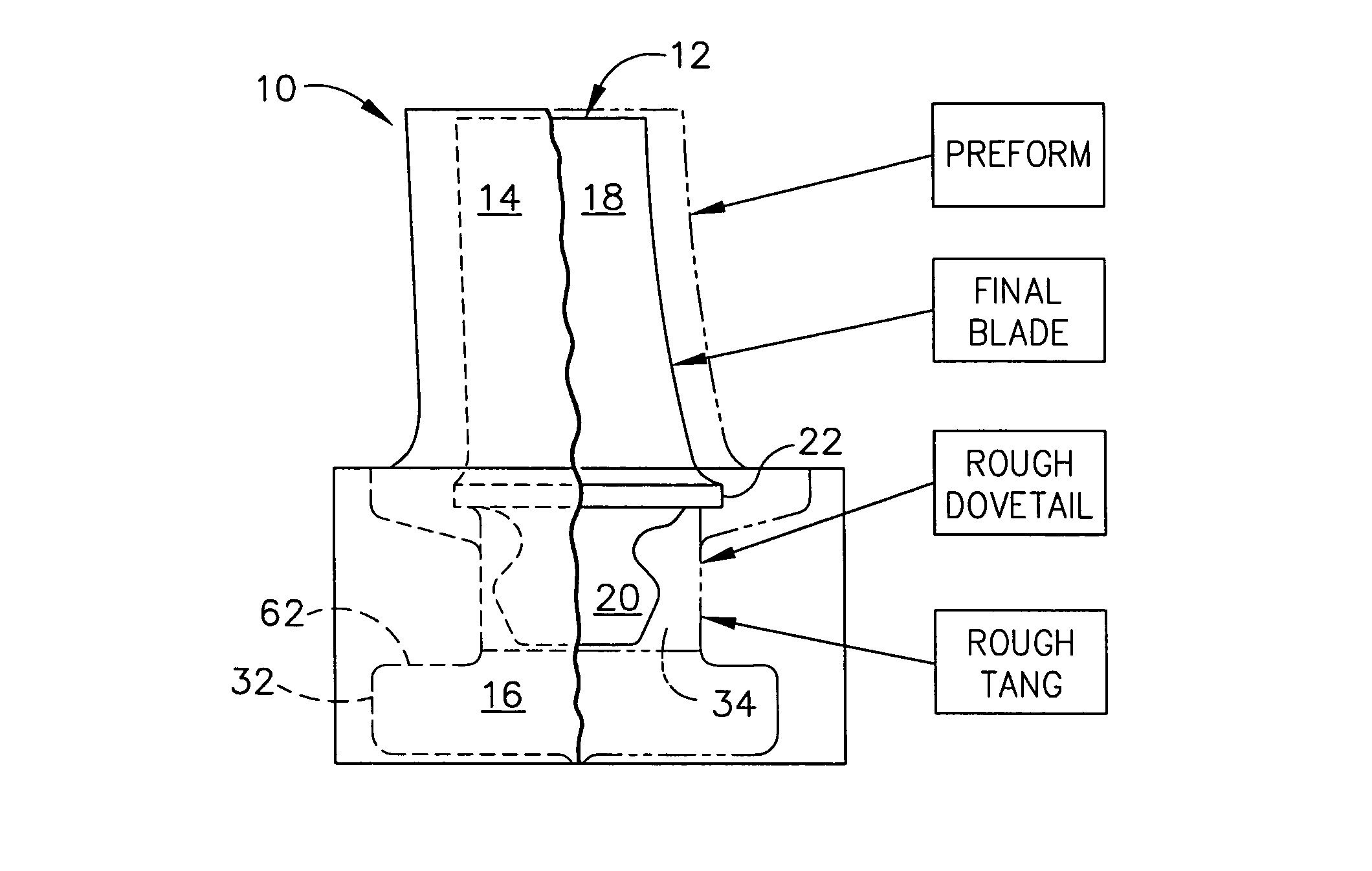
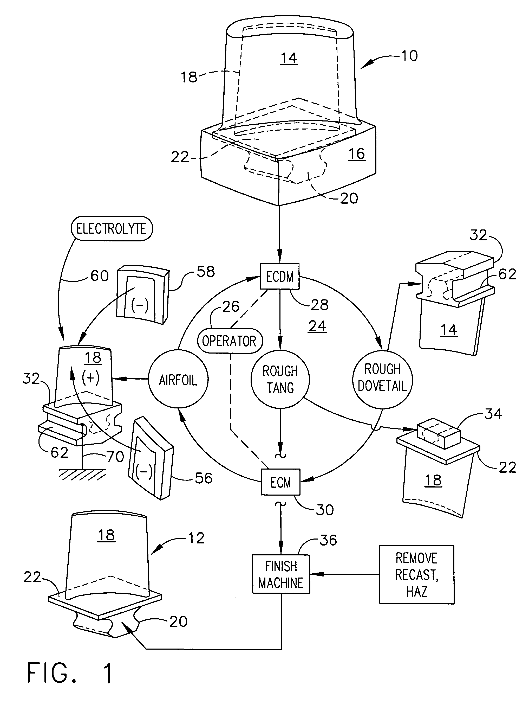
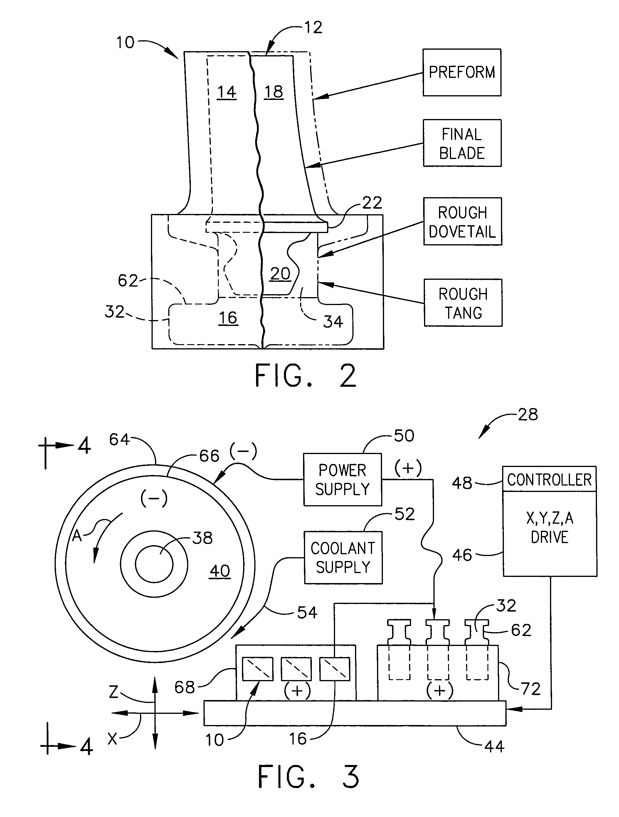
[0032]Illustrated in FIG. 1 is a workpiece or preform 10 which requires machining for making a final product such as a rotor blade 12 for use in a gas turbine engine (not shown). As indicated above, the typical gas turbine engine includes multiple stages of compressor rotor blades, such as the rotor blade 12, which are suitably mounted to the perimeter of a supporting rotor disk (not shown).

[0033]The preform 10 includes a first portion in the form of an airfoil stub 14 integrally formed with a second portion in the different form of a dovetail hub 16. The preform is formed of a suitable metal, such as a nickel superalloy having enhanced strength for the hostile environment of the gas turbine engine. The preform may be formed in any conventional manner such as the upsetting process described above.

[0034]The preform is suitably larger in size than the finally desired rotor blade 12, with the airfoil stub 14 corresponding with the final first part of the product such as an airfoil 18 o...


PUM

PropertyMeasurementUnit
electrical current capacityaaaaaaaaaa
diameteraaaaaaaaaa
shapeaaaaaaaaaa

Abstract

A preform includes an airfoil stub and a dovetail hub. The hub first undergoes electrochemical discharge machining to form a rough dovetail. The airfoil stub undergoes electrochemical machining to form an airfoil. The rough dovetail then undergoes electrochemical discharge machining to form a rough tang. The rough tang is finish machined to form a dovetail extending from the airfoil in a unitary rotor blade.

Description

BACKGROUND OF THE INVENTION[0001]The present invention relates generally to machining, and, more specifically, to electrical erosion machining.[0002]Modern gas turbine engines include multiple rows of rotor blades mounted to the perimeter of a supporting rotor disk. Compressor blades are used for pressurizing air in the compressor, and turbine blades are used for expanding combustion gases for powering the supporting disk.[0003]A high pressure turbine powers the compressor through a drive shaft extending therebetween. And a low pressure turbine powers an upstream fan in a turbofan aircraft engine application. In marine and industrial applications, the low pressure turbine powers an external drive shaft for powering a marine propeller or an electrical generator, for example.[0004]The gas turbine engine includes many stages of compressor and turbine blades. A multitude of such blades are therefore found therein. The blades in each stage or row are identical to each other, and typicall...

Claims


Application Information

Patent Timeline
Patent Type & Authority Patents(United States)
IPC IPC(8): B21D53/78B23P13/04
CPCB23H9/10Y10T29/49336Y10T29/49996Y10T29/49995
Inventor LAMPHERE, MICHAEL SCOTTWEI, BINROGENSKI, THOMAS WALTERDALE, DAN STEWARTJANSSEN, JONATHAN SEBASTIANWESSELS, JEFFREY FRANCIS
Owner GENERAL ELECTRIC CO
Features
  • R&D
  • Intellectual Property
  • Life Sciences
  • Materials
  • Tech Scout
  • Unparalleled Data Quality
  • Higher Quality Content
  • 60% Fewer Hallucinations
Learn More