Head-mounted display

a display and head technology, applied in the field of head-mounted displays, can solve the problems of inability to obtain the required force pressing against the head, inability to achieve comfortable fit, and easy slipping of the display by the viewer

Inactive Publication Date: 2012-08-07
CANON KK
View PDF9 Cites 12 Cited by
  • Summary
  • Abstract
  • Description
  • Claims
  • Application Information

AI Technical Summary

Benefits of technology

[0010]According to a typical embodiment of the present invention, a light-weight head-mounted display can be provided with which the problem of the strength of the members can be solved and a feeling of a comfortable fit can be obtained.

Problems solved by technology

Upon use of this structure to fasten the upper part of the viewer's head, the viewer feels as if the display easily slips off the head, and cannot obtain a feeling of comfortable fit.
Further, regarding the arm, because the distance between the point of application of force and the supporting point is long, the arm is distorted, and the required force pressing against the head cannot be obtained.
Further, when the strength of the frame and the arm is increased, the weight of the respective members is also increased, thus providing a poor fit and reducing comfort.

Method used


Image

  • Head-mounted display
  • Head-mounted display
  • Head-mounted display

Examples


Embodiment Construction

[0023]Preferred embodiments of the present invention will now be described in detail in accordance with the accompanying drawings.

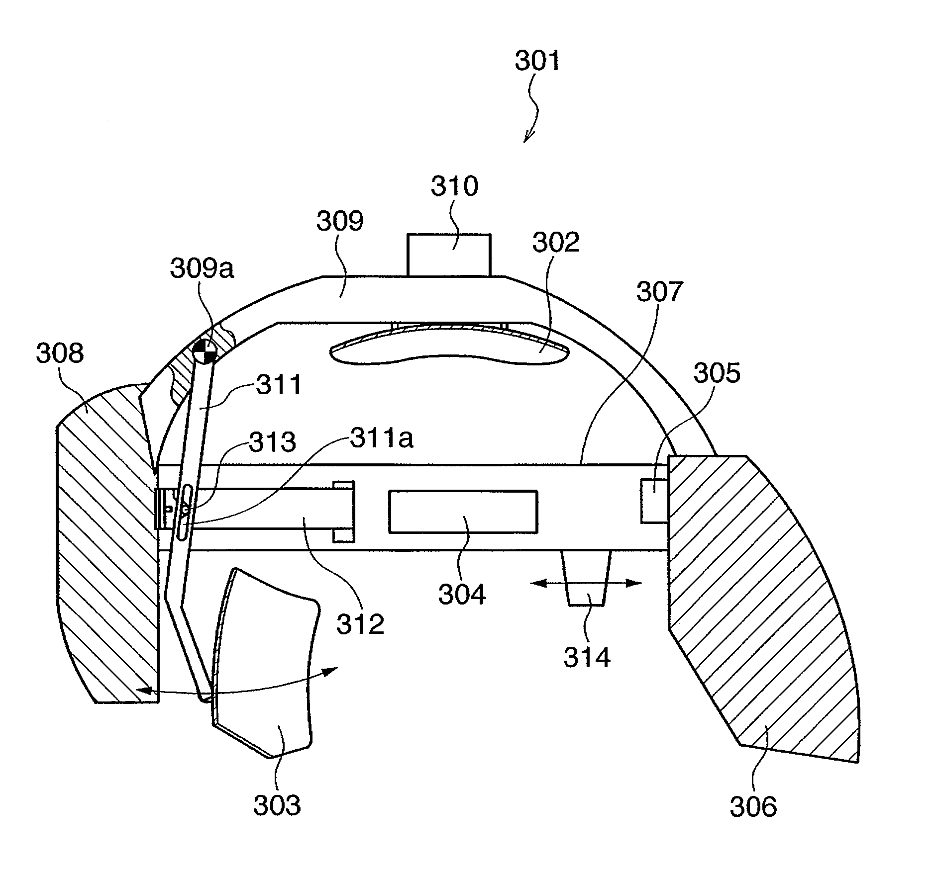
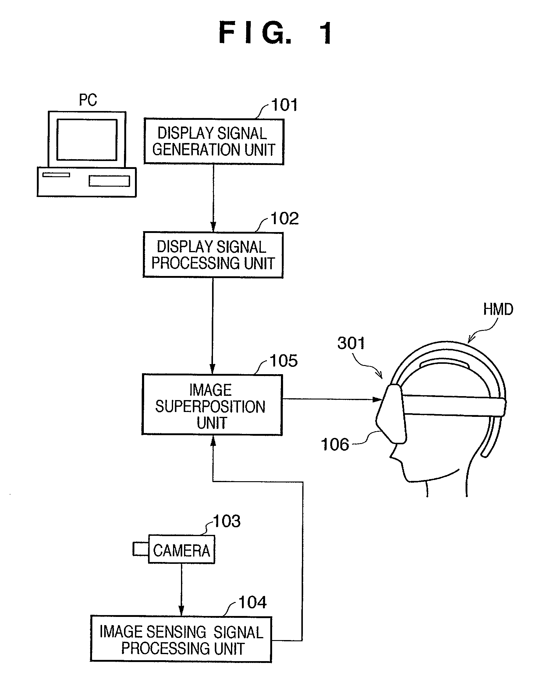
[0024]FIG. 1 is a block diagram showing an example of the configuration of a video display system according to an embodiment of the present invention. A display signal generation unit 101 generates a video signal of a CG or the like to be displayed on a video display unit 106 in a head-mounted display (HMD) 301. The display signal generation unit 101 generally is a computer such as a PC. The display signal generated by the display signal generation unit 101 is sent to a display signal processing unit 102. The display signal processing unit 102 converts the display signal generated by the display signal generation unit 101 to a signal format transmittable to the HMD 301.

[0025]An image sensing camera 103 having an image sensing device such as a CCD and an image sensing lens performs image sensing to obtain an external video image. Note that the direction of...


PUM


Abstract

A head-mounted device mounted on a wearer's head has a first pressing unit to press against the wearer's head from a position of his / her medulla, a second pressing unit to press against the wearer's head in an opposite direction to a pressing direction of the first pressing unit, and a mounting unit to mount the head-mounted device on the wearer's head by adjusting at least one of the first pressing unit and the second pressing unit.

Description

BACKGROUND OF THE INVENTION[0001]1. Field of the Invention[0002]The present invention relates to a head-mounted device. More particularly, the present invention relates to a head-mounted display, mounted on a viewer's head, to display a video image in front of the viewer, and relates to a structure for mounting the device on a viewer's head.[0003]2. Description of the Related Art[0004]In recent years, a head-mounted display which is mounted on a viewer's head is developed. This head-mounted display enlarges a video image displayed on a video display device such as a liquid crystal display and displays the enlarged image in front of the viewer, thereby enabling observation of a large screen video image.[0005]Japanese Patent Laid-Open No. 11-174988 discloses a video display as shown in FIG. 6. In this display, a pair of left and right LCDs 3 as two-dimensional video display devices to display video images corresponding to a viewer's left and right eyes are provided inside an exterior ...

Claims


Application Information

Patent Timeline
Patent Type & Authority Patents(United States)
IPC IPC(8): G09G5/00
CPCG02B27/017G02B27/0172G02B27/0176G02B7/002G02B2027/0138G02B2027/0187
Inventor ISHINO, TOSHIKINAKABAYASHI, TAKAAKISAITO, YOSHIHIROOKUMA, TOSHIYUKI
Owner CANON KK
Why Eureka
Try Eureka