Gas engine with pre-combustion chamber

a gas engine and pre-combustion chamber technology, applied in the direction of machines/engines, output power, mechanical apparatuses, etc., can solve the problems of long combustion time, self-ignition phenomenon (knocking), and loss of throttl

Inactive Publication Date: 2000-06-13
ISUZU MOTORS LTD
View PDF6 Cites 25 Cited by
  • Summary
  • Abstract
  • Description
  • Claims
  • Application Information

AI Technical Summary

Problems solved by technology

When a gas is drawn into the engine during the intake stroke and then compressed, the air-fuel mixture is compressed to high pressures and its temperature rises to so high a level that a self-ignition phenomenon (knocking) may result.
The greatest reasons why the engine with a pre-combustion chamber has a lower thermal efficiency than the direct injection type engine are that because the flames, after the primary combustion in the pre-combustion chamber, are ejected through the communication port connecting the main combustion chamber and the pre-combustion chamber and burned in the secondary combustion, the combustion time becomes long; that the communication port communicating the pre-combustion chamber with the main combustion chamber produces a throttle loss; and that a large air flow in the pre-combustion chamber results in a large heat dissipation loss.
In the gas engine with a pre-combustion chamber, because the air-fuel mixture generation energy and the ejection energy, essential for combustion, are produced by the throttling or diameter reduction of the pre-combustion chamber's communication port, the passage area of the communication port cannot be increased, resulting in a large pumping loss.
Further, because the mixture is made by a turbulent air flow, the thermal conductivity in the pre-combustion chamber is large increasing a cooling water loss.
In the vortex flow chamber type engines, the communication port connecting the pre-combustion chamber to the main combustion chamber is small and thus produces a throttle loss, reducing the engine output.
Because the communication port connecting the main combustion chamber and the pre-combustion chamber is provided at a cylinder center or at an outer circumferential position, the distance that the ejected flow must travel becomes longer, leaving the mixing of air and fuel in the main combustion chamber insufficient, which in turn will cause HC emissions and smoke.
Further, there is a problem that when a swirl-formed in the cylinder when the air is drawn in through the intake port-flows into the pre-combustion chamber through the communication port, the energy of the swirl cannot be fully utilized in the pre-combustion chamber because the communication port is throttled and inclined.

Method used


Image

  • Gas engine with pre-combustion chamber
  • Gas engine with pre-combustion chamber
  • Gas engine with pre-combustion chamber

Examples


first embodiment

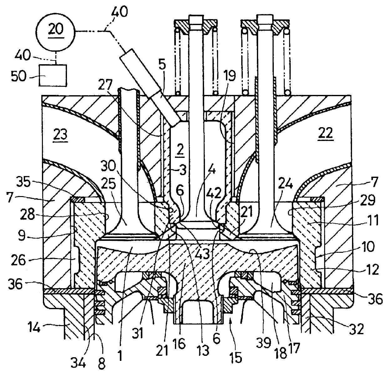
With reference to FIG. 1 and 2, the gas engine with a pre-combustion chamber of this invention will be described.

This gas engine with a pre-combustion chamber is operated in a diesel cycle that uses a gas fuel such as natural gas. In this gas engine with a pre-combustion chamber, a cylinder head 7 is secured to a cylinder block 14 through a gasket 36. In a small-diameter cavity 19 formed in the cylinder head 7 is installed a pre-combustion chamber structure 3 that forms a heat-insulated pre-combustion chamber 2. In a large-diameter cavity 9 formed in the cylinder head 7 is installed a head liner 10 that forms a heat-insulated main combustion chamber 1 on the cylinder 8 side. The gas engine with a pre-combustion chamber includes a cylinder liner 32 fitted in a bore 34 formed in the cylinder block 14; a piston 15 that reciprocates in the cylinder 8 formed by the cylinder liner 32; a main combustion chamber 1 formed by the cylinder 8 and a recess 39 in the piston top surface; and a com...
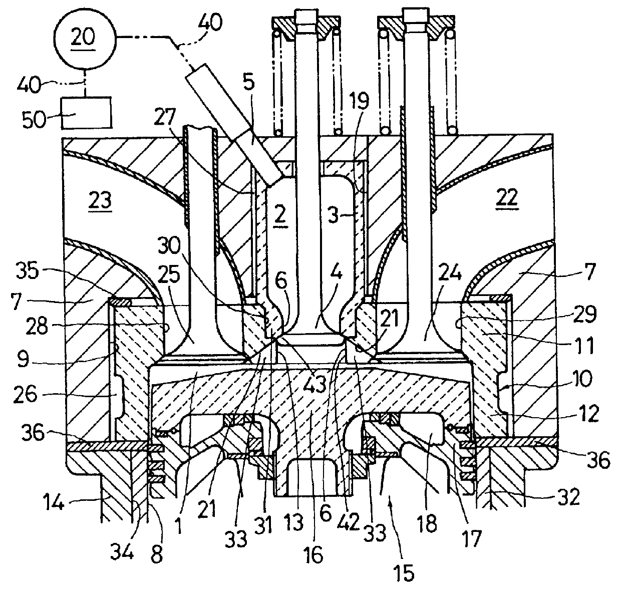
second embodiment

In the gas engine with a pre-combustion chamber, a guide portion 42 larger in diameter than the bevel portion 43 of the poppet valve constituting the control valve 4 is formed at the end portion of the main communication port 13 on the pre-combustion chamber 2 side. The sub-communication ports 21 are spaced from each other circumferentially around the main communication port 13 and extend from the guide portion 42 radially toward the cylinder periphery. The sub-communication ports 21 are formed as grooves 33 that are open on the main combustion chamber 1 side, and when the poppet valve is open, the outer circumferential surface of its bevel portion 43 adjusts the open area of the sub-communication ports 21 on the pre-combustion chamber 2 side.

Next, by referring to FIG. 5 and 6, a third embodiment of the gas engine with a pre-combustion chamber of this invention will be described. The third embodiment is similar to the previous embodiments except for the construction of the communica...

third embodiment

In the gas engine with a pre-combustion chamber of the third embodiment, the head liner 10 of the combustion chamber structure is formed with communication ports 37 rather than the main communication port and the sub-communication ports. The head liner 10 slightly protrudes into the main combustion chamber 1 of the cylinder 8 at almost the center of the head underside portion 11, with its front end portion closed to form a projected portion 38.

In this gas engine with a pre-combustion chamber, the head liner. 10 has the projected portion 38 at almost the center of the cylinder which projects into the main combustion chamber 1. The projected portion 38 of the head liner 10 is formed with a hole 30, in which a pre-combustion chamber structure 3 forming the pre-combustion chamber 2 is installed. At the central part of the hole 30 is formed a small-diameter hole portion 44. The wall of the projected portion 38 of the head liner 10 is formed with communication ports 37 that extend radiall...


PUM


Abstract

This gas engine with pre-combustion chambers. effectively uses ejection energy of flames and air-fuel mixtures ejected from the pre-combustion chambers into the main combustion chambers to shorten the combustion duration and thereby enhance performance. Installed in the cylinder head at the central part of the cylinders are pre-combustion chamber structures. that form pre-combustion chambers; Combustion chamber structures are formed with communication port that communicate the pre-combustion chambers with the main combustion chambers. Control valves are provided to open and close the communication ports. The communication ports comprise main communication ports and sub-communication ports formed around the main communication ports. The sub-communication ports are formed in the combustion chamber structures so that they extend radially toward the cylinder periphery.

Description

1. Field of the InventionThe present invention relates to a gas engine having a pre-combustion chamber in a cylinder head and using a gas fuel such as natural gas.2. Description of the Prior ArtIn conventional gas engines having a pre-combustion chamber in the cylinder head, the pre-combustion chamber is made fuel-rich for ignition and combustion to ensure combustion in lean regions in a main combustion chamber thereby stabilizing combustion. The gas engine, however, uses a natural gas as fuel, that is, the fuel is in a gas phase. When a gas is drawn into the engine during the intake stroke and then compressed, the air-fuel mixture is compressed to high pressures and its temperature rises to so high a level that a self-ignition phenomenon (knocking) may result. Normally, the natural gas must have a compression ratio of less than 12 to avoid self-ignition. As for the thermal efficiency, the smaller compression ratio means a lower thermal efficiency.In the gas engine with a pre-combus...

Claims


Application Information

Patent Timeline
Patent Type & Authority Patents(United States)
IPC IPC(8): F02B19/02F02B19/00F02B19/14F02B43/00F02D13/02F02D15/04F02M21/02
CPCF02B19/02Y02T10/125Y02T10/12
Inventor MATSUOKA, HIROSHIKAWAMURA, HIDEONAKASHIMA, KENROU
Owner ISUZU MOTORS LTD
Why Eureka
Try Eureka