
Glass panel

a glass panel and glass technology, applied in the field of glass panels, can solve the problems of cracks and damage of sharp edges, cracks from sharp edges, etc., and achieve the effects of improving the strength of low melting glass, superior thermal insulation performance, and superior strength

Inactive Publication Date: 2007-07-17
NIPPON SHEET GLASS CO LTD +1
View PDF16 Cites 61 Cited by
  • Summary
  • Abstract
  • Description
  • Claims
  • Application Information

AI Technical Summary

Benefits of technology

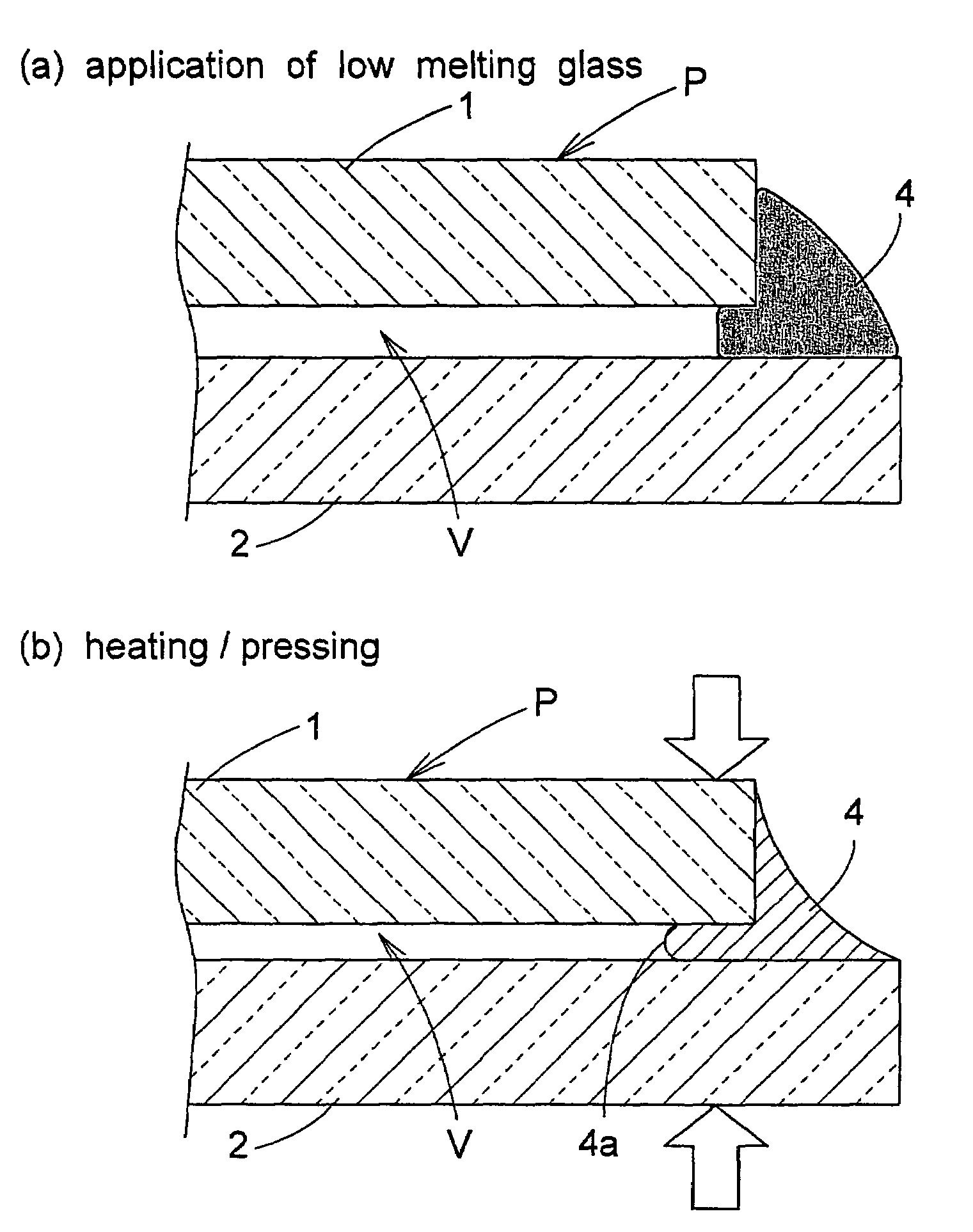
[0012]And, even when a wind pressure or the like acts on the faces of the glass sheets, tending to displace the glass sheets closer to each other, this stress will be dissipated toward the bulging portion located at the center between the two glass sheets. So, there hardly occurs any stress concentration. Consequently, the strength of the low melting glass at the peripheral edges of the glass sheets can be improved significantly.
[0014]With this construction, since the adjacent face is formed as a curved face bulging toward the gap, compared with a construction wherein the adjacent face is formed as a face bulging toward the gap at an acute angle, the above construction can avoid stress concentration even more reliably. Hence, the strength of the low melting glass at the peripheral edges of the glass sheets can be further improved.
[0016]With this construction, since spacers are provided in the gap between the pair of glass sheets and the gap is sealed under a depressurized state, with the depressurization of the gap, it is possible to provide a glass panel having distinguished thermal insulation performance.
[0017]And, with such glass panel, the atmospheric pressure is constantly applied to the faces of its glass sheets, thus causing problem in the strength of the low melting glass. However, as described above, the strength of the low melting glass can be improved. As a result, it is possible to provide a glass panel which has the superior thermal insulation performance and also superior strength.

Problems solved by technology

As a result, the sharp edged portions 4c would often be cracked and damaged.
Moreover, when the sharp edged portions 4c are damaged, due to the characteristics of the low melting glass vulnerable to brittle fracture, the crack would develop from that damaged portion.

Method used


Image

  • Glass panel
  • Glass panel
  • Glass panel

Examples


Embodiment Construction

[0027]An embodiment of a glass panel relating to the present invention will be described with reference to the accompanying drawings.

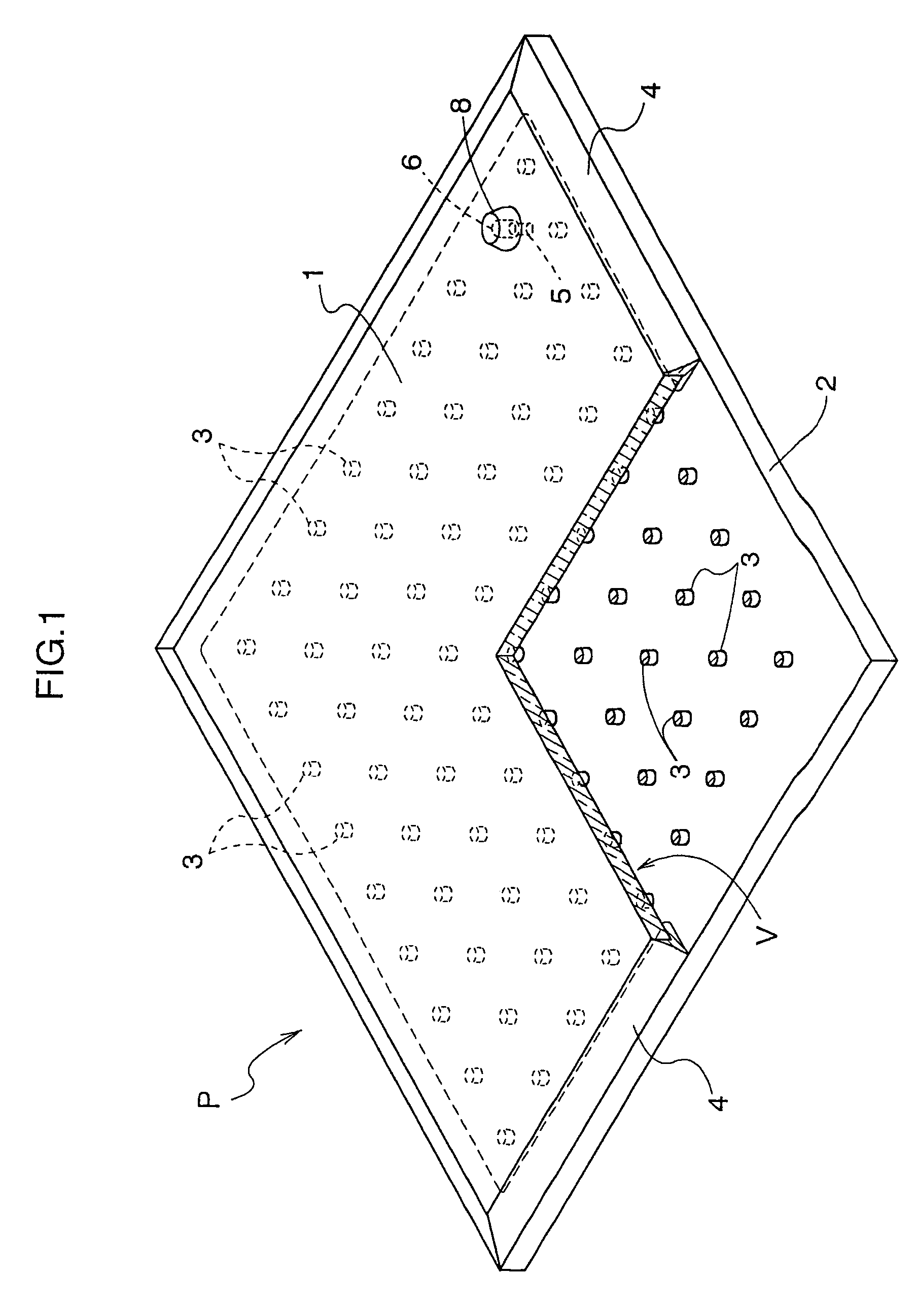
[0028]An example of such glass panel is a double glazing. This double glazing P, as shown in FIG. 1, includes a pair of glass sheets 1,2 and a number of spacers 3 interposed between faces of the two glass sheets 1,2, so that the two glass sheets 1, 2 are disposed in opposition to each other with forming a gap V therebetween. Peripheral edges of the two glass sheets 1,2 are bonded together with a low melting glass 4 which has a lower melting point than the two glass sheets 1, 2 and which also has a low gas permeability, and the gap V between the glass sheets 1, 2 is sealed under a depressurized state.

[0029]Each of the two glass sheets 1, 2 employs a transparent float glass sheet having a thickness ranging 2.65 mm to 3.2 mm. And, the gap V between the glass sheets 1, 2 is depressurized to 1.33 Pa (1.0×10⁻² Torr) or lower.

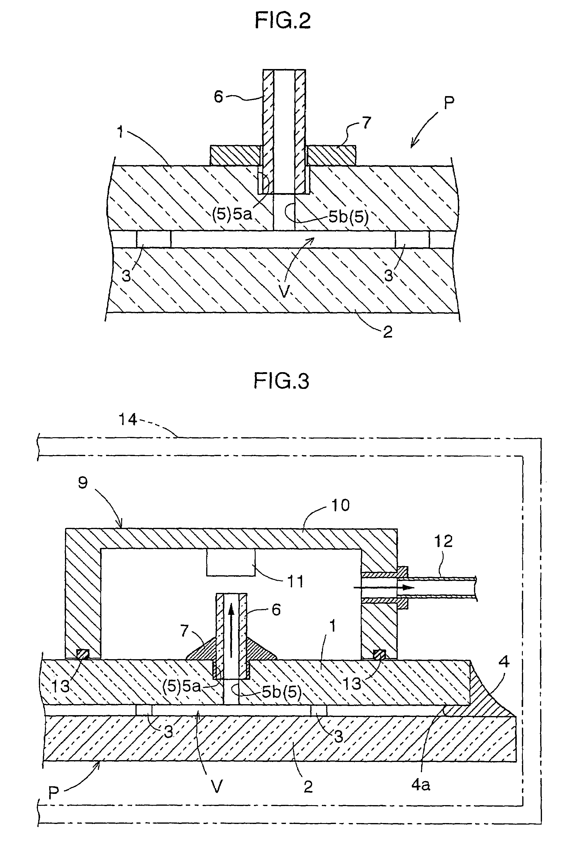
[0030]Referring to the depressuri...


PUM

PropertyMeasurementUnit
viscosityaaaaaaaaaa
stress concentrationaaaaaaaaaa
diameteraaaaaaaaaa

Abstract

A glass panel comprising: a pair of glass sheets (1), (2) disposed in opposition to each other via a gap (V) therebetween, peripheral edges of the two glass sheets (1), (2) being bonded with low melting glass (4) for sealing the gap (V);wherein in a cross section substantially normal to faces of the two glass sheets, (1), (2), an adjacent face (4a) of the low melting glass (4) adjacent the gap (V) has a center portion thereof between the two glass sheets (1), (2) bulging toward the gap (V).

Description

CONTINUATION DATA[0001]This application claims priority from Japanese Application No JP2001-204547 filed Jul. 5, 2001, which is a continuation of Internatioal Application PCT / JP02 / 06760, an international filing date of Jun. 3, 2002, which designated the United States, was amended on Feb. 4, 2003, and is now abandoned.TECHNICAL FIELD[0002]The present invention relates to a glass panel including a pair of glass sheets disposed in opposition to each other with a gap formed therebetween, peripheral edges of the two glass sheets being bonded with low melting glass for sealing the gap.BACKGROUND ART[0003]The low melting glass is often used for sealing the gap of such glass panel as above because it has superior adhesive property to e.g. metal solder. Conventionally, the low melting glass in the form of paste would be applied to the peripheral edges of the two glass sheets and heated to 480° C. or higher, thereby to render the low melting glass into melted state. Then, it would be cooled t...

Claims


Application Information

Patent Timeline
Patent Type & Authority Patents(United States)
IPC IPC(8): E06B3/00E04C2/54C03C27/06C03C27/12E06B3/663E06B3/677
CPCC03C27/06E06B3/6612E06B3/6775E06B3/66333Y10T428/24777Y02B80/24Y02B80/22Y02A30/249
Inventor MINAAI, TETSUOCOLLINS, RICHARD EDWARDNG, NELSON
Owner NIPPON SHEET GLASS CO LTD
Learn More