Temperature Altering Garment and Methods of Use Thereon

a technology of temperature altering garments and garments, applied in the field of clothing, can solve the problems of inability to simultaneously apply thermal transfer elements to more than a few people, the method has significant disadvantages, and the person is unable to simultaneously engage in other activities that require the use of hands, so as to prevent injury to muscles, keep body parts warm, and avoid weakening the engagement

Active Publication Date: 2008-08-28
SNAPBAC LLC A DELAWARE LLC
View PDF21 Cites 56 Cited by
  • Summary
  • Abstract
  • Description
  • Claims
  • Application Information

AI Technical Summary

Benefits of technology

[0016]There are many advantages to the various embodiments of the present invention. An advantage of one embodiment is the ability to adjustably secure a thermal transfer element to any body part covered by the garment. In this embodiment, the location of the thermal transfer element is adjustable over substantially an entire surface of an article of clothing because the fastener on the article of clothing is not fixed in a single location. Instead, in this embodiment, the fastener substantially covers an entire surface of the article of clothing. Thus a user of this embodiment of the present invention can precisely and adjustably target any body part covered by the article of clothing, instead of only specific, unchangeable locations.
[0017]Another advantage of an embodiment of the present invention is the ability to adjustably secure a thermal transfer element to an article of clothing multiple times without weakening the strength of the engagement between the fasteners. Other systems, which use adhesives to secure thermal transfer elements to an article of clothing, do not have this advantage because the adhesive weakens after every adhesion. Eventually, after multiple adhesions, the adhesive will no longer hold the thermal transfer element to the article of clothing. The engagement between fasteners of an embodiment of the present invention, however, does not so weaken due to repeated use.
[0018]Another advantage of an embodiment of the present invention is that it allows a person to apply a thermal transfer element to a hard to reach area, such as the back, without requiring the assistance of another. The person can simply secure the thermal transfer element to the back of the article of clothing before putting on the article of clothing. In other systems, it is very awkward or cumbersome to apply a thermal transfer element to the back without the assistance of another.
[0019]Another advantage of an embodiment of the present invention is that it allows a user to apply a thermal transfer element to a body part without occupying the hands. Thus, the user can engage in activities that require the use of one or both hands while a thermal transfer element is held against a body part. A further, related advantage is the ability to hold multiple thermal transfer elements, including both hot and cold thermal transfer elements simultaneously, to multiple body parts. Manual systems are limited by the number of thermal transfer elements the person can hold in the hands. The present invention, however, is not so limited.
[0020]A further related advantage of an embodiment of the present invention is the ability to engage in an athletic activity while a thermal transfer element is held against a body part. An athlete wearing a garment of the present invention is able to keep body parts warm during periods of inactivity, and need not remove the garment prior to resuming the athletic activity. Wearing the garment during the athletic activity can also prevent injury to muscles by keeping them warm. Alternatively, an athlete can cool parts of the body during strenuous activity to prevent overheating. Furthermore, a thermal transfer element secured to a body part can act as padding for that body part. Finally, after the athletic activity, the garment can be used for treatment of sore muscles.
[0021]Yet another advantage of an embodiment of the present invention is the ability to press a thermal transfer element against a body part. When the article of clothing snugly fits the body of the wearer, and when the thermal transfer element is secured inside the article of clothing, the snug fit presses the thermal transfer element against the body part. The term “snug fit” means that the article of clothing is tight on the wearer's body, having little or no slack in the material. The term “press,” as used in this context, means a force exerted on the thermal transfer element and toward the body of the wearer. This pressure increases the efficiency of heat transfer by increasing the surface area of the thermal transfer element in contact with the body part, because any gaps between the surface of the thermal transfer and the body part will be flattened out. Furthermore, pressure is also helpful for preventing swelling of an injured body part when a cold pack is applied.

Problems solved by technology

This method has significant disadvantages.
Additionally, a person cannot alone simultaneously apply thermal transfer elements to more than a few areas on the body, since a person is only able to use two hands to hold the packs in place.
Finally, because the hands of a person using this method will be occupied, the person will be unable to simultaneously engage in other activities that require use of the hands.
First, the person's movement can be restricted by attachment of thermal transfer elements to certain commonly treated parts, such as the knee.
Additionally, a user is likely to find it cumbersome to hold the pack in place with one hand while simultaneously trying to use a strap or other means to secure the pack in place.
Furthermore, attaching a thermal transfer element too tightly can impede circulation and cause tissue damage by disrupting blood flow through the treated body part.
Finally, it is difficult to physically attach a thermal transfer element to certain body parts, such as the back, without engaging the assistance of another.
It turns out that using pockets to position thermal pads, however, is not an especially good solution.
But of course devices using that concept can be extremely uncomfortable.

Method used


Image

  • Temperature Altering Garment and Methods of Use Thereon
  • Temperature Altering Garment and Methods of Use Thereon
  • Temperature Altering Garment and Methods of Use Thereon

Examples


Embodiment Construction

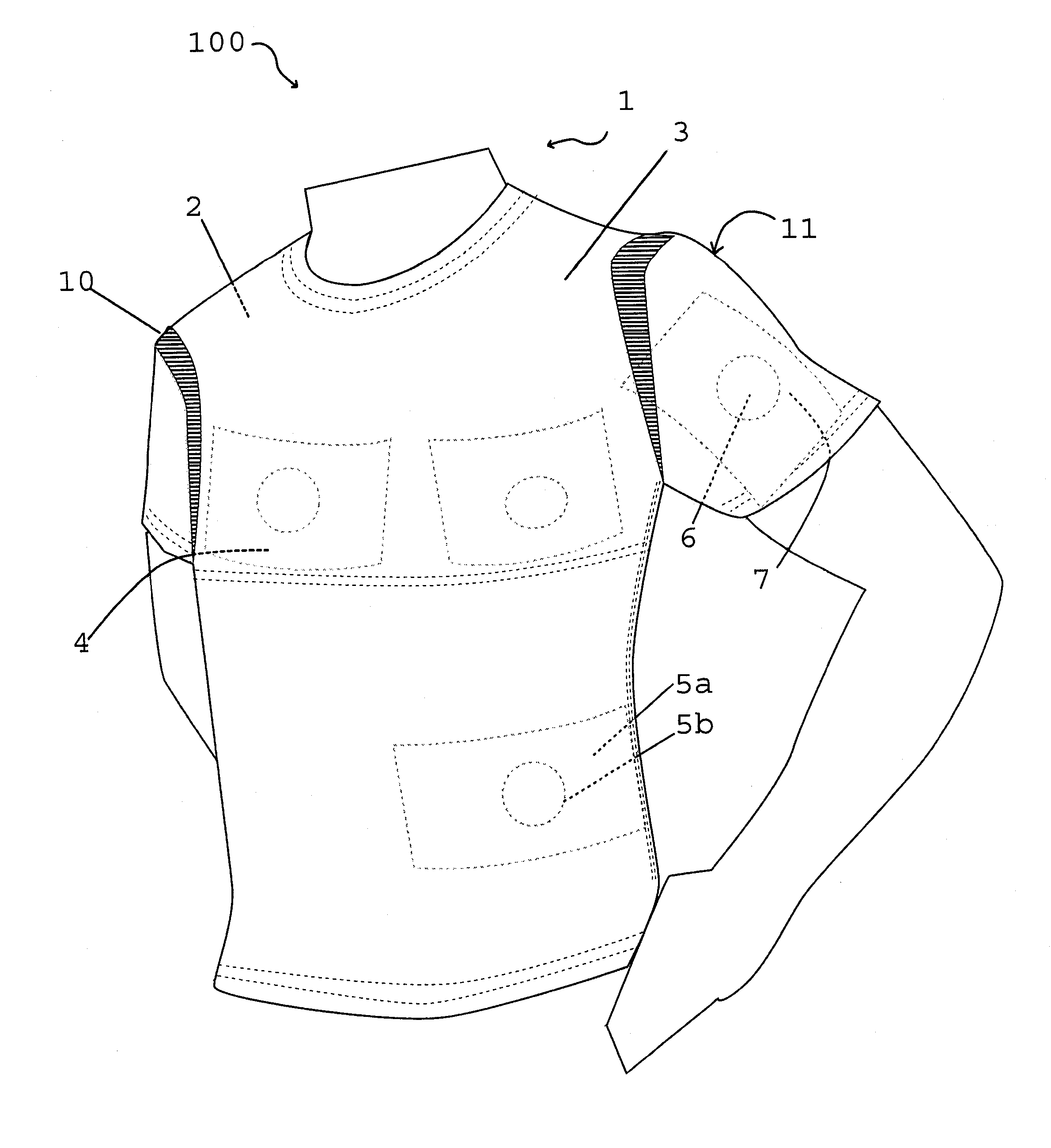
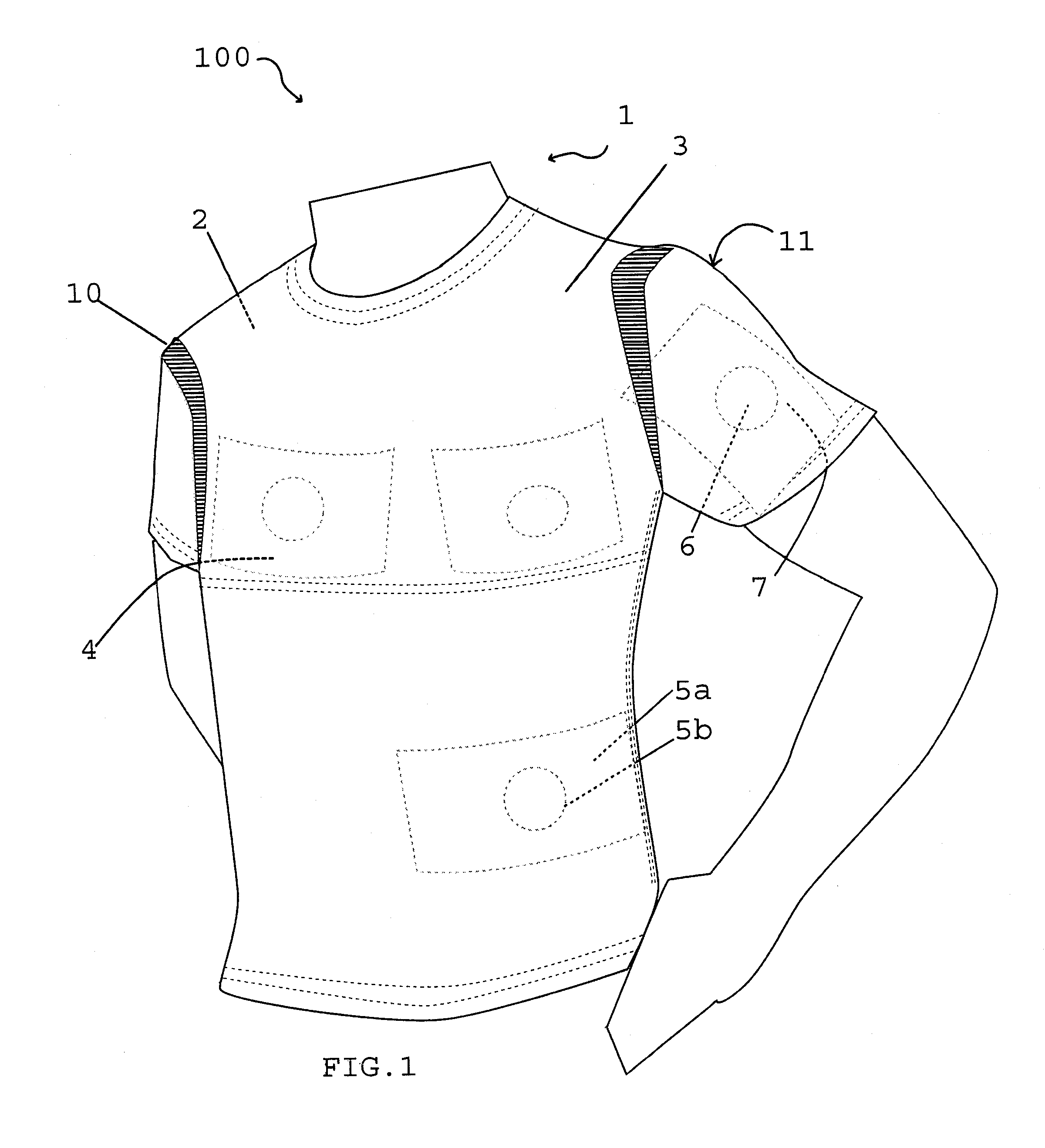
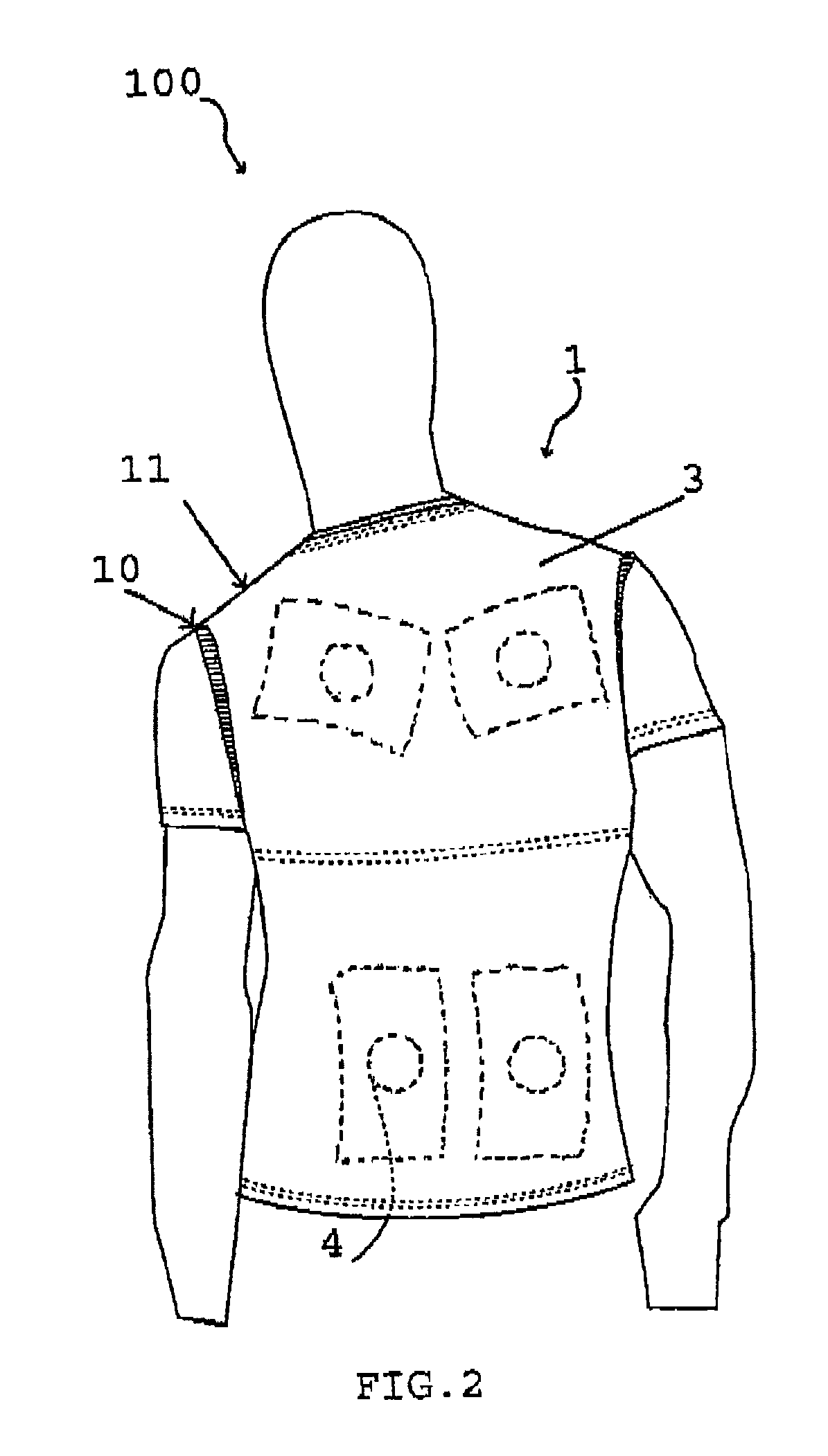
[0046]FIGS. 1 to 3 generally depict a garment 100 having a first layer 10, an outer layer 11, a thermal transfer element 4, a first fastener 5A, and a second fastener 5B. The garment 100 is the entire combination; the article of clothing 1 is the piece of apparel to which thermal transfer elements are secured.

[0047]An engagement between the first fastener 5A and the second fastener 5B removably and adjustably secures the thermal transfer element 4 to any location 6 on the interior surface 2 of the outer layer 11 of the article of clothing 1. “Removably and adjustably” secured means that the thermal transfer element can be removed without damaging the fasteners or otherwise dismantling the garment, and can be reattached in a different location. After attachment, heat transfer takes place between the thermal transfer element 4 and a body part 7 in contact with the location 6 on the article of clothing 1 where the thermal transfer element 4 is secured. The location 6 is “in contact” wi...


PUM


Abstract

Human clothing has inner and outer flexible layers that define a space sufficiently large to position a thermal transfer element in any of multiple, non-overlapping positions. The space and the thermal transfer element preferably have cooperating sides of a hook-and-loop attachment. All suitable items of clothing are contemplated, but especially a shirt, jacket or pants that appear to others as a substantially normal garment. Each space has one or more openings, in either the inner or outer layers, and preferably at the shoulders or sides of the torso, or at the pocket areas of pants. The spaces are preferably large, not only relative to the size of a corresponding thermal transfer element, but also to the size of the garment. Thermal transfer elements are preferably disposed in pouches having a thermal insulation on that side, and have only a very thin, thermally transmissive, fabric on the other side.

Description

CROSS-REFERENCE TO RELATED APPLICATION[0001]This application is a CIP of U.S. utility application Ser. No. 11 / 804,552 filed May 18, 2007, which claims priority to U.S. provisional application No. 60 / 838,666 filed Aug. 17, 2006 and also claims priority to application Ser. No. 10 / 559,860 filed Dec. 6, 2005, which is a US national phase of International application no. PCT / US04 / 031540 filed Sep. 27, 2004, which claims priority to U.S. application Ser. No. 10 / 807,695 filed Mar. 24, 2004.FIELD OF THE INVENTION[0002]The field of the invention is clothing that accommodates heating and cooling pads.BACKGROUND[0003]It is known to heat or cool parts of the human body to prevent or treat injuries, relieve pain, improve flexibility, warm a person in a cold environment, cool a person in a hot environment, and so forth. A common method for heating or cooling a body part is to contact the part with a hot or cold pack, generically referred herein as a thermal transfer element.[0004]There are many w...

Claims


Application Information

Patent Timeline
Patent Type & Authority Applications(United States)
IPC IPC(8): A41D1/00A41D27/20H05B1/00A61F7/00
CPCA41B2300/32A41D13/005A41D27/20A61F7/02F25D2400/26A61F2007/0233A61F2007/0238A61F2007/0249F25D3/08A61F2007/0001
Inventor NILFORUSHAN, ALIBELLO, KEVIN
Owner SNAPBAC LLC A DELAWARE LLC
Why Eureka
Try Eureka