Satellites and signal distribution methods and off-set pattern for sending signals

a satellite and signal technology, applied in the field of satellite and signal distribution methods, can solve the problems of increasing the cost of service, reducing the transmission efficiency of the satellite system, and large expansion of the useful bandwidth via spot beams, so as to improve the transmission efficiency, reduce the inefficiencies caused, and double the capacity

Inactive Publication Date: 2012-08-07
SPECTRUM FIVE
View PDF24 Cites 2 Cited by
  • Summary
  • Abstract
  • Description
  • Claims
  • Application Information

AI Technical Summary

Benefits of technology

[0009]The invention, however, provides alternative spot-beams which can carry a DMA, thus relieving heavily congested spot-beams. This is referred to as “diffusion.” The invention proposes methods for minimizing “straddling” and / or for promoting the “diffusion” of traffic away from saturated spot-beams.
[0011]The use of spot-beam patterns is efficient in serving point-to-point users, such as individual subscribers in satellite based Internet service, called “Broadband,” because every subscriber is located somewhere in one of the beams and, consequently, can always receive the appropriate signals. To provide the maximum capacity the same patterns depicted in FIGS. 1 and 3, as discussed above, are provided on the orthogonal polarization, thus doubling the capacity, i.e., each spot-beam is coaxial with the corresponding spot-beam on the orthogonal polarization. In this case, a given DMA may be served by the spot-beam of either polarization.
[0012]By utilizing the satellites, satellite constellations, and methods of the invention, a satellite television service can minimize the inefficiencies caused by “straddling” and improve the efficiencies of transmission by promoting “diffusion” and still provide service to the entire CONUS. The invention embodies the creation of two almost identical antenna spot-beam coverage patterns, called Pattern 1 and Pattern 2 such as depicted in the Figures, for example FIGS. 4-5. However, the Pattern 2 is “offset” from Pattern 1, either in translation or in rotation, or both, in order to attain the desired coverage characteristics. Pattern 2 also is orthogonally polarized to Pattern 1. Patterns 1 and 2 might be generated by a single phased array antenna or by one or more reflector-type antennas. The antennas generating the Patterns 1 and 2 may be contained on one satellite or two or more satellites. In the latter case, some orbital redundancy is achieved, providing total coverage but reduced service should one of the satellites fail.
[0013]In another aspect of the invention, the problem of straddling and spot-beam saturation is minimized in an antenna system using one or more satellites) with two spot-beam patterns, one on each polarization, to “off-set” the spot-beam pattern of one antenna with respect to the other antenna. The off-set may be any amount in only one direction or in two orthogonal directions, called a translation, in order to obtain the desired composite pattern. Alternatively, Pattern 2 might be rotated relative to Pattern 1 or a combination of translation and rotation of Pattern 2 relative to Pattern 1 might have advantageous characteristics. An example is given in FIGS. 3 and 4, in which the spot-beam pattern of FIG. 3 (and FIG. 1) is shifted slightly south and superimposed on the original, similar pattern. Thus, Pattern 1 remains the same (as in FIGS. 1 and 3) but Pattern 2 is created by shifting the orthogonal pattern of FIGS. 1 and 3 south by a one half-coverage beamwidth. The double cross-hatched spot-beam in the center of FIG. 4 is the spot-beam of interest, and is the original central spot beam depicted in FIG. 3. However Pattern 2, on the orthogonal polarization, now provides three spot-beams that each, partially, cover the central spot-beam of interest. These three spot-beams from Pattern 2, arbitrarily labeled NE, NW and S, intersect with a triple crossover in the very center of the spot-beam of interest from Pattern 1. These three spot-beams cover substantial portions of the edge of the spot-beam of interest. Any DMAs straddling the spot-beam of interest in the NE, NW or S directions may be wholly within one of the three spot-beams of Pattern 2. Thus, the effects of “straddling” can be much reduced. The three spot-beams of Pattern 2, NE, NW and S also cover three of the six triple crossovers of the original Pattern 1, also helping to minimize “straddling.” This characteristic, the minimization of straddling, is an important capability of the invention and the use of the Offset Pattern described here.
[0014]Further, if the spot-beam of interest is heavily loaded with TV signals these may be offloaded into neighboring spot-beams (spot-beams NE, NW and S); this capability is called “diffusion.” In the example of FIG. 3, if a DMA is wholly within the spot-beam of interest but is also within the NE, NW or S spot-beams of Pattern 2, that DMA can be transferred to the appropriate spot beam of Pattern 2. Thus, that DMA is removed from the spot-beam of interest in Pattern 1, thereby reducing the capacity of that spot-beam, and moved to a spot-beam of Pattern 2. This characteristic is called “diffusion” and is an import capability of the Offset Pattern.

Problems solved by technology

Thus, the expansion of the useful bandwidth via spot-beams can be large.
This overlapping of DMAs between beams, called “straddling,” reduces the transmission efficiency of the satellite system by increasing the number of times a given TV signal must be transmitted by the satellite, thereby increasing the cost of service.
In addition, all of the DMAs within the spot-beam of FIG. 2 (on one or two polarizations) must be carried because there may be no alternative spot-beam illuminating this area.

Method used


Image

  • Satellites and signal distribution methods and off-set pattern for sending signals
  • Satellites and signal distribution methods and off-set pattern for sending signals
  • Satellites and signal distribution methods and off-set pattern for sending signals

Examples


example 1

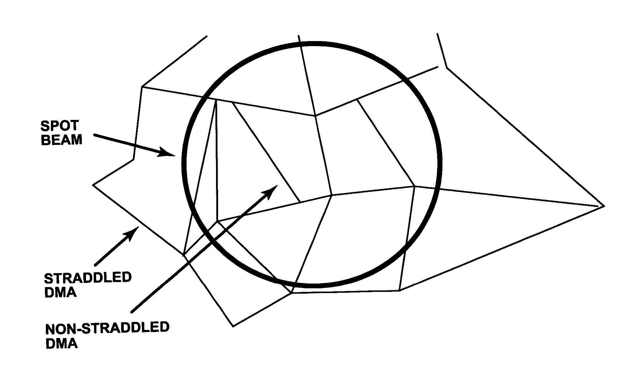
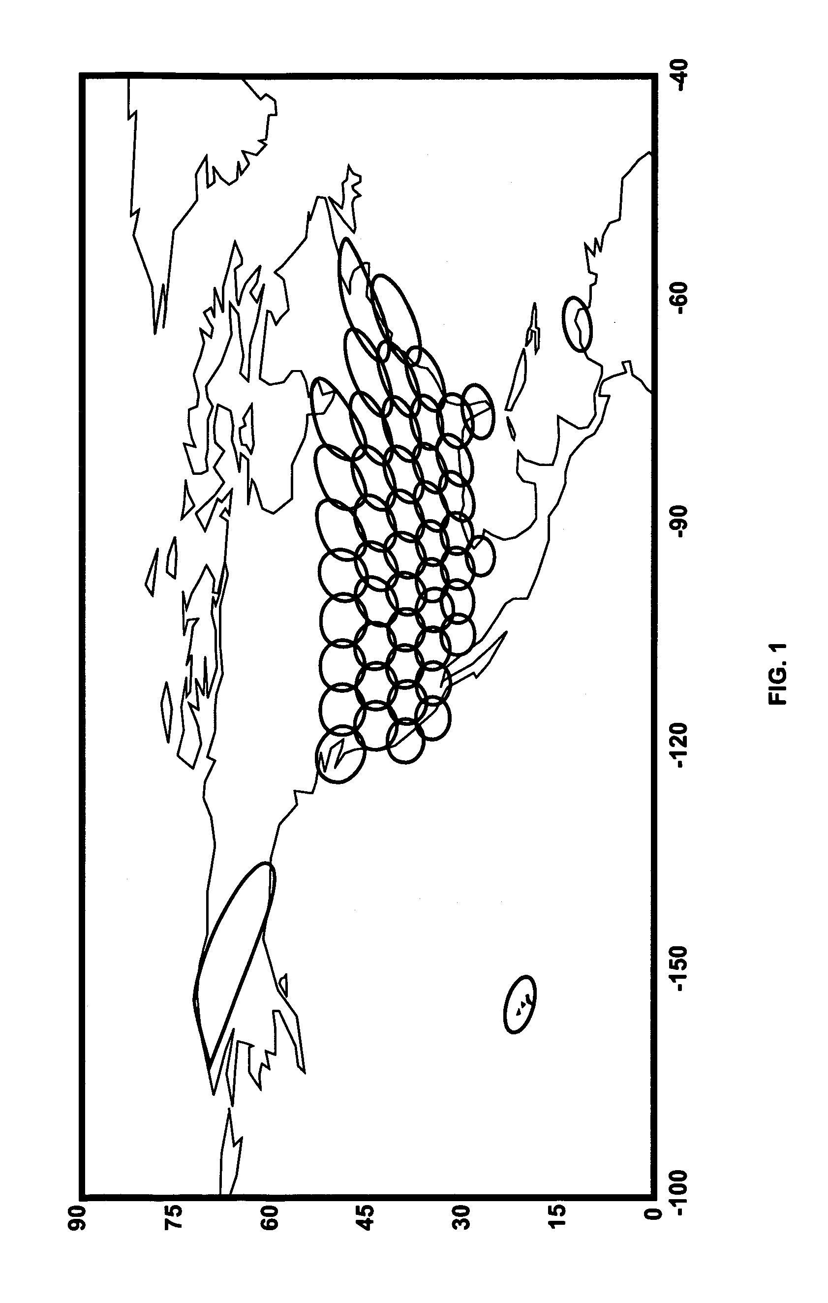
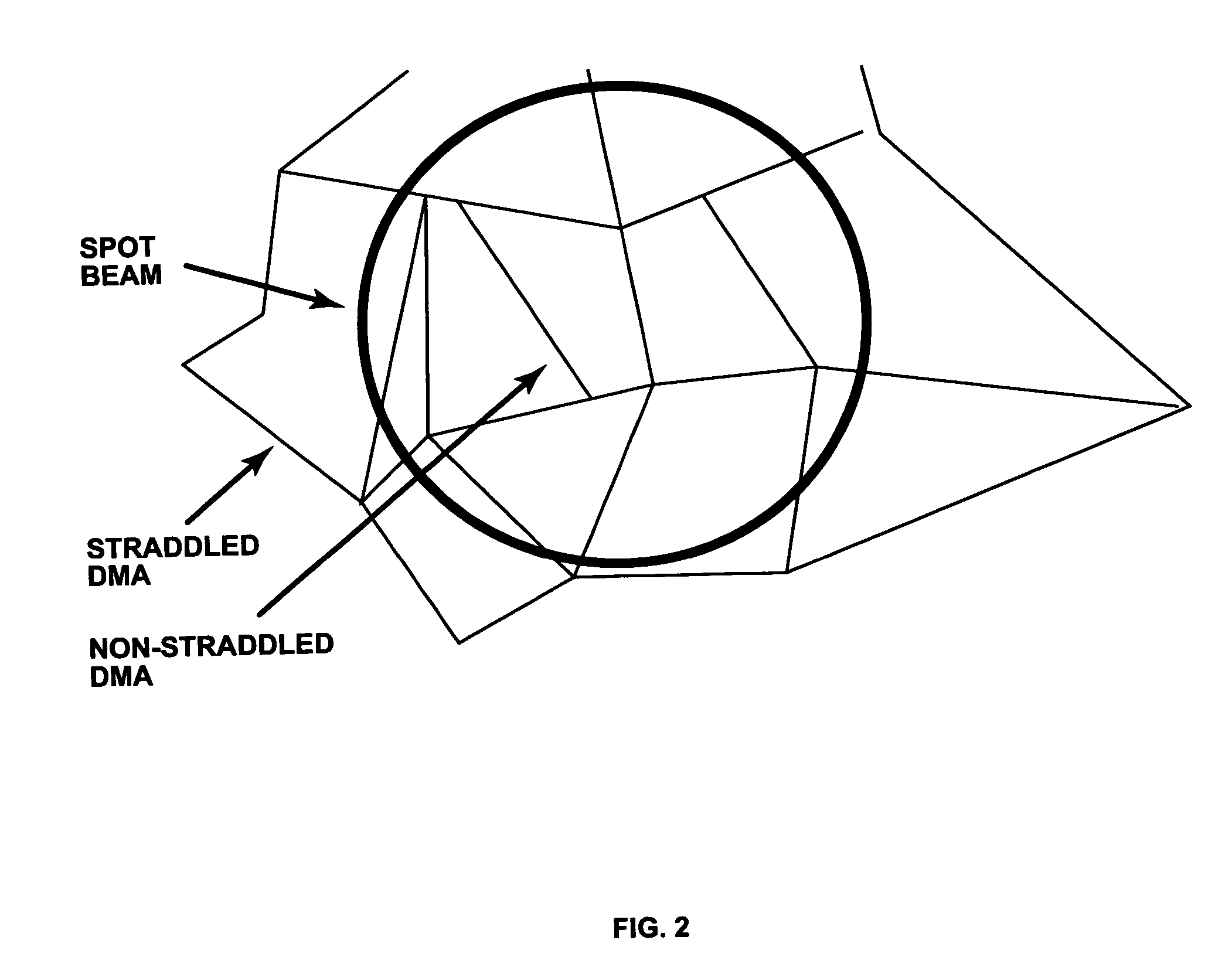
[0040]The inventor has studied a spot beam system serving the U.S. making use of conventional spot-beam technology, called the “Conventional Spot-Beam System” and an “Offset Spot-Beam System” of the invention. In the Conventional Spot-Beam system there were 48 co-axial spot-beams serving the continental United States (CONUS) on two polarizations (Patterns 1 and 2 are coaxial but orthogonally polarized). In the Offset Spot-Beam System of the invention, there were also 48 spot-beams serving CONUS on one polarization and 48 spot-beams serving CONUS on the orthogonal polarization but Pattern 2 was offset, as described herein; Pattern 2 was moved south by one half of a coverage beamwidth (as indicated in FIGS. 3 and 4). All 215 DMAs and approximately 1,600 TV channels are assigned to the individual spot-beams to avoid straddling to the maximum possible extent, and to promote diffusion in the saturated New York City spot-beam. The results of the two analyses, for a conventional spot-beam ...

example 2

[0045]A public safety activity involving recovery and search and rescue is normally conducted within state and county boundaries having stringent requirements for survivable two-way communications. A system of one or more multiple spot-beam satellites and simple uplink earth stations can provide the required survivable communications. Coverage of the counties and states could embody the Offset Patterns described herein to improve the communications efficiency by minimizing straddling and promoting diffusion. While counties and states are considered here, any mosaic of geographic areas might benefit from the invention.

[0046]One skilled in the art can devise and create numerous other examples according to this invention. Examples may also incorporate additional imaging, thermometry, and other elements known in the art. One skilled in the art is familiar with techniques and devices for incorporating the invention into a variety of devices and of designing improved devices through the u...


PUM


Abstract

The invention relates to methods, systems, and satellites that employ an off-set pattern of spot-beams to transmit signals or television signals over a desired area of the earth. In one example, a heavily populated metropolitan area in the continental United States is covered by at least two patterns of spot-beams, where the patterns are off-set to one another by a lateral or translational displacement, rotation, or both. The off-set patterns can be used in conjunction with existing satellites and systems and incorporated into new satellites and systems. The methods reduce problems associated with the straddling of subscriber areas caused by local-into-local requirements, and advantageously allow increased spot-beam capacity, and the reduction in earth uplink stations.

Description

FIELD OF INVENTION[0001]The invention concerns the use of geostationary satellite communications with multiple spot-beam satellite antennas serving a multitude of ground-based subscribers. Methods and satellite systems are described that substantially improve the satellite transmission efficiency, increasing the transmission data rate and reducing the cost of satellite transmission.BACKGROUND OF INVENTION[0002]There are a variety of systems and proposals for satellite television and data broadcasting or broadcasting over defined geographic or customer service areas. One proposal employs multiple spot-beam patterns to essentially cover an entire service area. However, there are requirements that complicate the operation of multiple spot-beam systems. One example is the “local-into-local” service, where the satellite operator must collect television broadcast signals from a specific television market area, called a “designated market area” or DMA (as defined by Nielsen Media Research ...

Claims


Application Information

Patent Timeline
Patent Type & Authority Patents(United States)
IPC IPC(8): H04B7/185
CPCH04B7/2041
Inventor KIESLING, JOHN D.
Owner SPECTRUM FIVE
Why Eureka
Try Eureka