System and method for reducing particulate matter emission in diesel exhaust gas

a technology of particulate matter and diesel exhaust gas, which is applied in the direction of machines/engines, mechanical equipment, separation processes, etc., can solve the problems of reducing the effectiveness and reliability the inability to effectively adapt the flow distribution of the aftertreatment device, and the operation of the conventional application employing diesel engines, etc., to reduce the emission of particulate matter, reduce the density of the cross-sectional area, and reduce the effect of particulate matter

Active Publication Date: 2012-08-14
GE GLOBAL SOURCING LLC
View PDF39 Cites 8 Cited by
  • Summary
  • Abstract
  • Description
  • Claims
  • Application Information

AI Technical Summary

Benefits of technology

[0007]Another embodiment of the present invention provides a method for reducing particulate matter emission in diesel engine exhaust gas. The method includes providing a diesel particulate filter including a plurality of diesel particulate filter units. The providing step includes selectively configuring a distinct cross-sectional area density of a plurality of channels of each diesel particulate filter unit. The providing step further includes separating adjacent channels of the plurality of channels with a respective wall, where each wall of the diesel particular filter unit has a respective thickness. The providing step further includes vacating a distinct ratio of the area of each wall within the diesel particulate filter unit with a plurality of pores. The providing step further includes aligning the plurality of channels of each diesel particulate filter unit in a direction of the diesel engine exhaust gas. Additionally, the method includes engaging a respective cross-sectional region of the diesel engine exhaust gas including particulate matter with a respective diesel particulate filter unit of the diesel particulate filter.
[0008]Another embodiment of the present invention provides an aftertreatment system for chemically altering the chemical emissions in engine exhaust gas. The aftertreatment system includes an aftertreatment substrate configured to engage a respective cross-sectional region of the engine exhaust gas including the chemical emissions. The aftertreatment system further includes a catalyst component configured to coat the aftertreatment substrate. The aftertreatment substrate, with the catalyst component coating is configured to reduce particular chemical emissions in the engine exhaust gas as the engine exhaust gas passes through the aftertreatment substrate.

Problems solved by technology

Conventional applications employing diesel engines, such as locomotives, do not have optimized flow distributions necessary for effectively adapting aftertreatment devices and have them operate at peak performance.
However, since the flow distribution of diesel exhaust gas is non-uniform at the cross-section 154, and the aftertreatment device 156 provides equal resistance across its cross-section, a majority of the diesel exhaust gas 150 at the center cross-section 154 may flow through or load the aftertreatment device in a manner that reduces effectiveness and reliability of the aftertreatment device(s).

Method used


Image

  • System and method for reducing particulate matter emission in diesel exhaust gas
  • System and method for reducing particulate matter emission in diesel exhaust gas
  • System and method for reducing particulate matter emission in diesel exhaust gas

Examples


Embodiment Construction

[0024]Reference will now be made in detail to the embodiments consistent with the invention, examples of which are illustrated in the accompanying drawings. Wherever possible, the same reference numerals used throughout the drawings refer to the same or like parts.

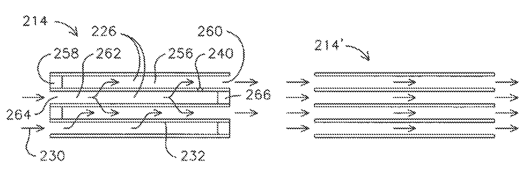
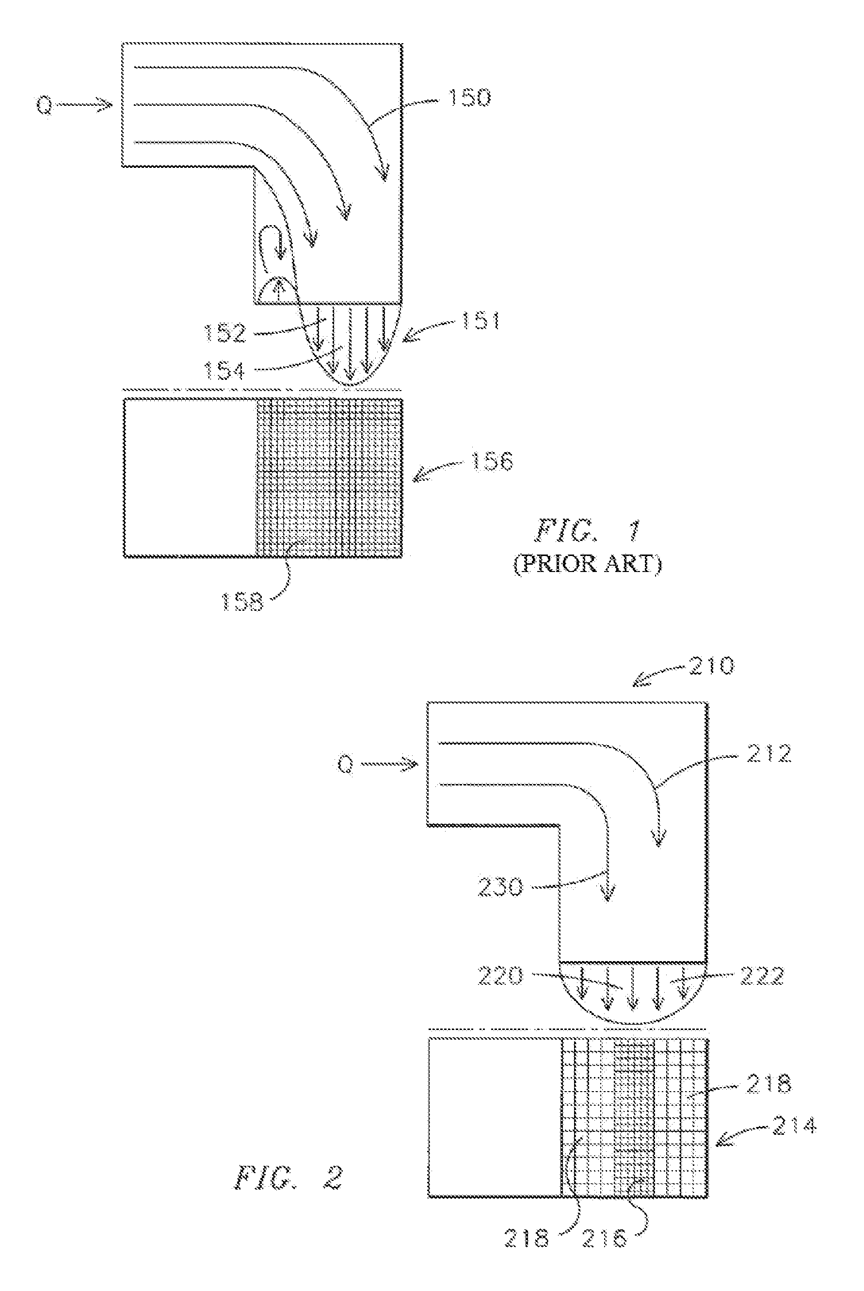
[0025]As illustrated in the exemplary embodiment of FIG. 2, a system 210 is illustrated to reduce particulate matter emission in diesel engine exhaust gas 212. Aftertreatment systems are used to reduce particulate matter within the diesel engine exhaust gas, chemically alter the engine exhaust gas, or perform any other operation appreciated by one of skill in the art, to reduce any non-uniformity in the exhaust flow. One example of an aftertreatment system is a diesel particulate filter, and will be discussed in the following exemplary embodiments. Another example of an aftertreatment system is catalyst substrates, and they will be discussed in the embodiments following those embodiments discussing the diesel particulate f...


PUM

PropertyMeasurementUnit
thresholdaaaaaaaaaa
temperatureaaaaaaaaaa

Abstract

An aftertreatment system is provided for reducing particulate matter emission and chemical emissions in diesel engine exhaust gas. The system includes a diesel particulate filter including a plurality of diesel particulate filter units configured to engage respective cross-sectional regions of the diesel engine exhaust gas including particulate matter. Each diesel particulate filter unit includes a plurality of channels aligned in a flow direction of the diesel engine exhaust gas. The channels are selectively configured with a distinct cross-sectional area density. Additionally, each diesel particulate filter unit includes a plurality of walls separating adjacent channels of the plurality of channels, where the walls have a respective thickness. A plurality of pores are configured to vacate a distinct ratio of the area of the walls.

Description

[0001]This application is related to U.S. patent application Ser. Nos. 11 / 838,277 and 11 / 838,296, filed concurrently herewith. Each of the foregoing applications is incorporated by reference herein in their entirety.FIELD OF THE INVENTION[0002]This invention relates to diesel exhaust gas, and more particularly to a system and method for reducing particulate matter emission in diesel exhaust gas.BACKGROUND OF THE INVENTION[0003]Diesel engines have been extensively used in various applications, such as locomotives, for example. Diesel engine exhaust gas is typically outputted from the engine (or a turbocharger connected to the diesel engine) and directed to an output, such as to the atmosphere for a locomotive diesel engine, for example.[0004]Conventional applications employing diesel engines, such as locomotives, do not have optimized flow distributions necessary for effectively adapting aftertreatment devices and have them operate at peak performance. For example, as illustrated in ...

Claims


Application Information

Patent Timeline
Patent Type & Authority Patents(United States)
IPC IPC(8): F01N3/00F01N3/02B01D46/00B01D50/00
CPCF01N3/0222F01N2330/06F01N2330/48Y02T10/20Y02T10/12
Inventor LU, SHUGUANGPRIMUS, ROYGLENN, WILLIAM DOUGLAS
Owner GE GLOBAL SOURCING LLC
Why Eureka
Try Eureka