Chain disk conveyor corner housing

a conveyor and disk technology, applied in the direction of mechanical conveyors, animal husbandry, irrigation and aquaria, etc., can solve the problems of mold growth, affecting the rotation of the wheel, and affecting the operation of the conveyor

Active Publication Date: 2012-08-21
THE GSI GRP LLC
View PDF9 Cites 10 Cited by
  • Summary
  • Abstract
  • Description
  • Claims
  • Application Information

AI Technical Summary

Problems solved by technology

However, particulate matter can get lodged in the housing and begin to interfere with the rotation of the wheel.
This can lead to mold growth which is obviously an undesirable condition in animal confinement systems.
This will cause unnecessary load on the chain loop and drive system, and can cause significant wear on the chain disks.
Furthermore, with the housing being opaque, it is difficult to determine the status of the wheel assembly (i.e. how full the wheel area is of particulate matter) and therefore requires a difficult process of disassembly to ensure clean and smooth operation.

Method used


Image

  • Chain disk conveyor corner housing
  • Chain disk conveyor corner housing
  • Chain disk conveyor corner housing

Examples


Embodiment Construction

[0018]The following detailed description illustrates the claimed invention by way of example and not by way of limitation. This description will clearly enable one skilled in the art to make and use the claimed invention, and describes several embodiments, adaptations, variations, alternatives and uses of the claimed invention, including what I presently believe is the best mode of carrying out the claimed invention. Additionally, it is to be understood that the invention is not limited in its application to the details of construction and the arrangements of components set forth in the following description or illustrated in the drawings. The claimed invention is capable of other embodiments and of being practiced or being carried out in various ways. Also, it is to be understood that the phraseology and terminology used herein is for the purpose of description and should not be regarded as limiting.

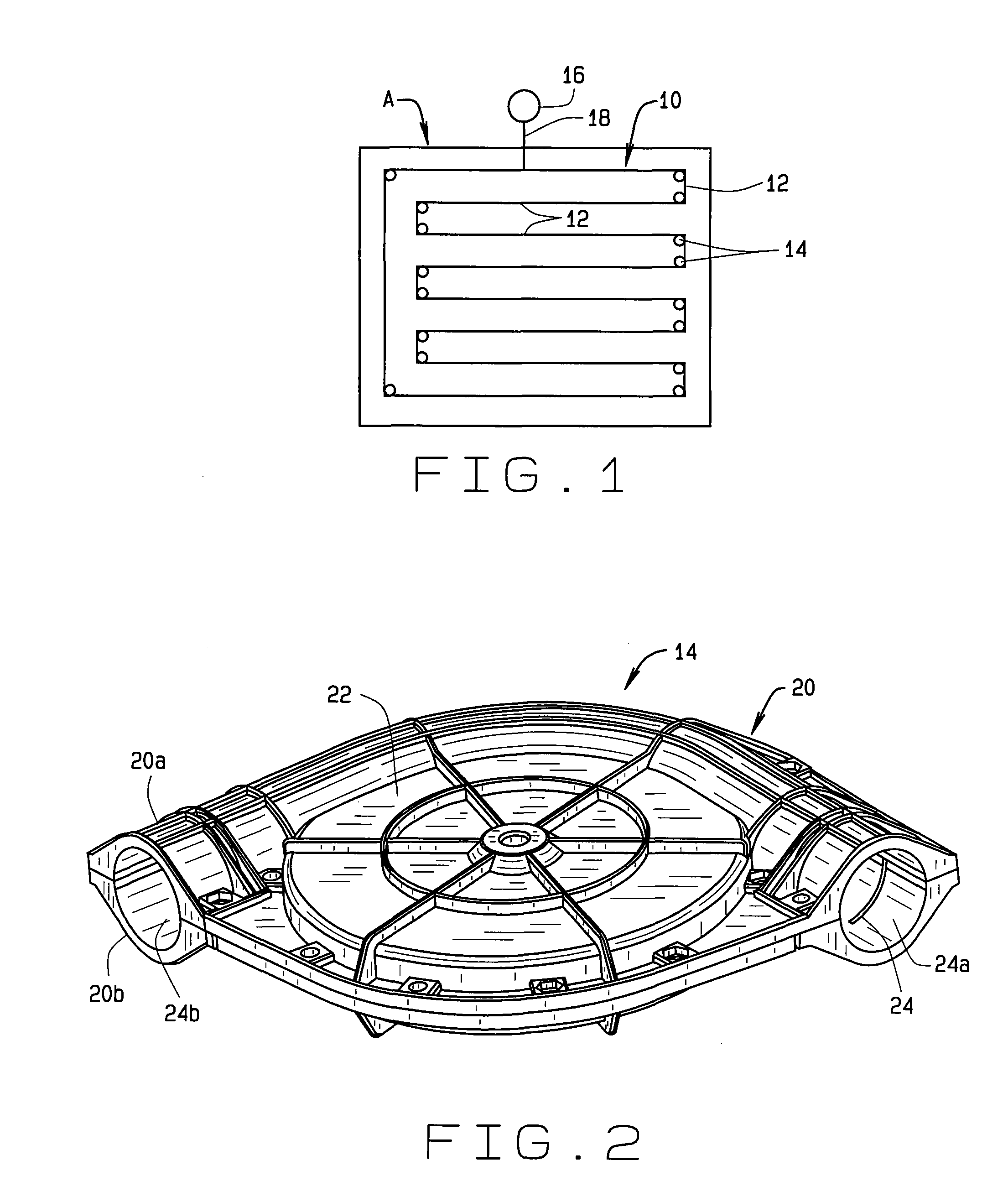
[0019]An animal feed system 10 in an animal house A is shown schematically in FIG. ...


PUM


Abstract

A corner assembly for a tube conveyor system comprises a housing defining a wheel receiving area and a flow path defining an angle and having ports at opposite ends of said flow path. A wheel is rotatably received in the wheel receiving area. The wheel comprises a rim having an upper surface and a lower surface; at least one pair of spaced apart channels formed in at least one of the upper and lower surfaces of the rim; and at least one flapper pivotally mounted to said wheel inside of said rim. The flapper is freely movable between a first position in which the flapper is aligned with a wall of one of the channels and a second position in which the flapper is aligned with a wall of the other of the channels. Thus, when the wheel rotates, the flapper will sweep any material in the wheel receiving area towards and through one of the channels and into the flow path.

Description

CROSS-REFERENCE TO RELATED APPLICATIONS[0001]This application claims priority to U.S. Provisional Application No. 61 / 146,718 filed Jan. 23, 2009, and which is incorporated herein by reference.STATEMENT REGARDING FEDERALLY SPONSORED RESEARCH OR DEVELOPMENT[0002]Not Applicable.BACKGROUND OF THE INVENTION[0003]This disclosure relates to chain disk conveyors (sometimes called tube conveyors, puck conveyors or drag chain conveyors) and, in particular, to a wheel assembly or corner housing for use in such conveyor systems.[0004]Chain disk conveyors typically comprise a plurality of disks dispersed a along a chain. The disks are generally perpendicular to the chain. The chain of disks is received within a tube assembly and is moved through the tube assembly to move particulate material, such as animal feed, through the tube assembly. A main advantage chain disk conveyors is that they provide an enclosed conveying system that can operate at any angle, in any plane and from point to point re...

Claims


Application Information

Patent Timeline
Patent Type & Authority Patents(United States)
IPC IPC(8): B65G31/04
CPCB65G19/14B65G23/04
Inventor EVERSOLE, BRAD
Owner THE GSI GRP LLC
Why Eureka
Try Eureka