
Fluid flow indicator with automatic alarm timer for high pressure/low flow applications
a technology of automatic alarm timer and flow indicator, which is applied in the direction of liquid/fluent solid measurement, instruments, transportation and packaging, etc., can solve the problems of not being able to support the weight of the piston, the performance of the grille to suffer, etc., and achieves the effect of reducing the pressure needed, quick and easy installation, and reducing the force of the return spring
- Summary
- Abstract
- Description
- Claims
- Application Information
AI Technical Summary
Benefits of technology
Problems solved by technology
Method used
Image

Examples
Embodiment Construction
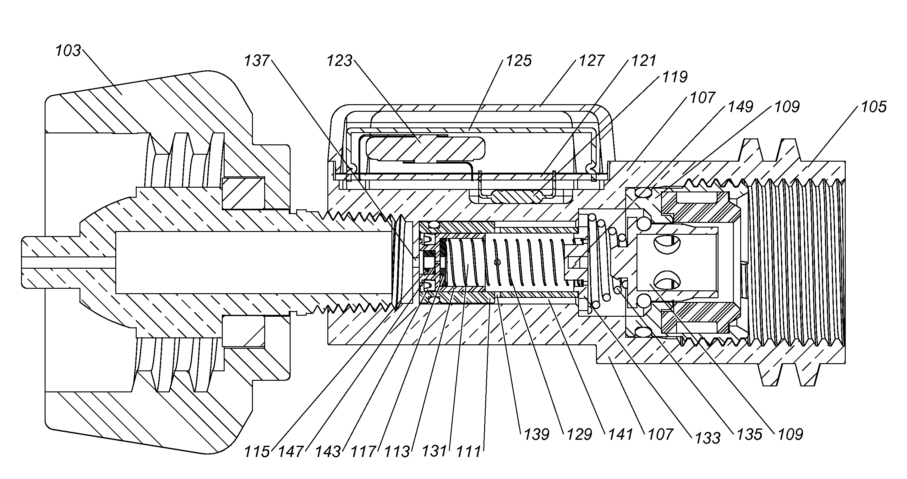
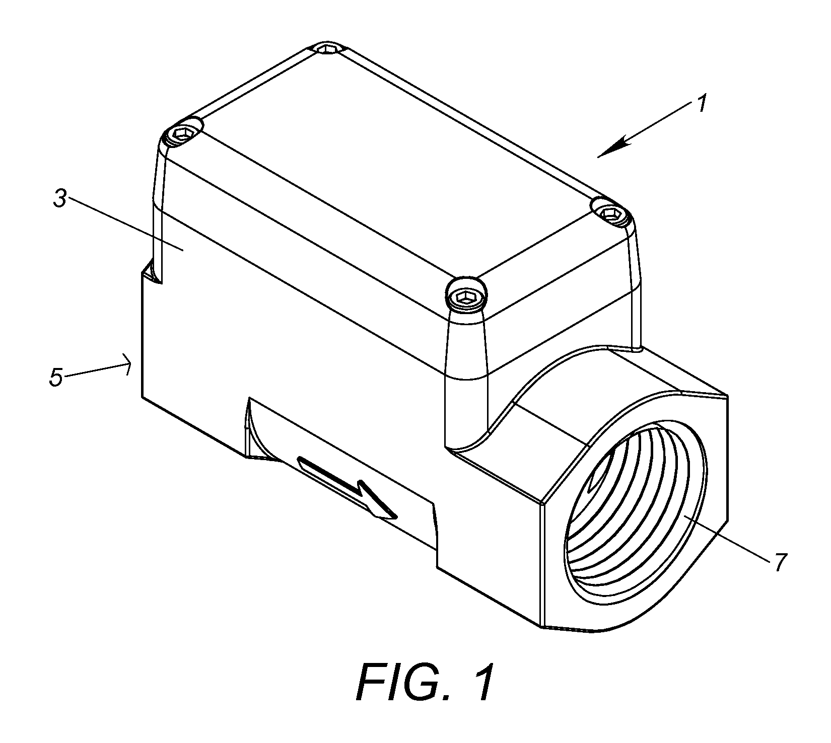
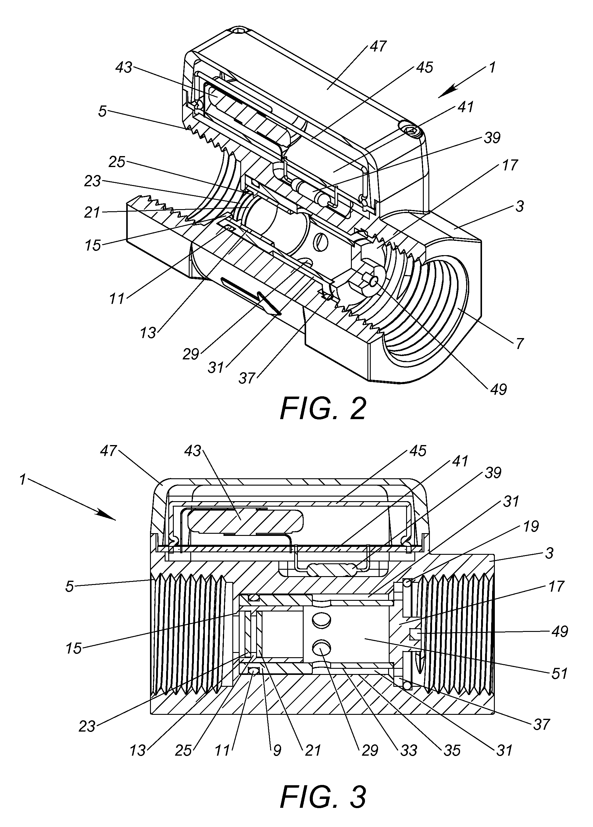
[0036]Shown in FIGS. 1 thru 5 is a fluid / gas flow switch 1 constructed in accordance with the present invention and configured for installation and use downstream of a typical gas grill appliance pressure regulator, or for use with household natural gas, where both the pressure and flow of gas is extremely low. The gas flow switch 1 includes an outer housing 3 with a threaded gas inlet port 5 and threaded outlet port 7. Gas flow switch 1 is therefore adapted to be threadably and sealably connected in vertical orientation (with inlet port 5 below the outlet port 7) inline with the gas line leading to the gas grill, downstream of the pressure regulator.
[0037]As shown in FIGS. 2 thru 5, the outer housing 3 includes an interior bore or chamber extending therethrough within which inner cylinder 9 is seated in sealed relation via o-ring 11. Inner cylinder 9 in turn carries piston 13 within its confines in close, free-floating slip-fit relation. Adjacent the inlet end of the flow switch 1,...
PUM
 Abstract
Description
Claims
Application Information