Fluid flow indicator with automatic alarm timer for low pressure/low flow applications

a technology of automatic alarm timer and flow indicator, which is applied in the direction of service pipe system, fire alarm, instruments, etc., can solve the problems of not being able to support the weight of the piston, the performance of the grill to suffer, etc., and achieves the effect of reducing the pressure needed, quick and easy installation, and reducing the force of the return spring

Active Publication Date: 2009-07-02
STRUYK DAVID
View PDF41 Cites 9 Cited by
  • Summary
  • Abstract
  • Description
  • Claims
  • Application Information

AI Technical Summary

Benefits of technology

[0018]It is the goal of this invention to provide an inexpensive, convenient to use, and easily installed low loss / low flow gas flow switch which provides a warning signal after a predetermined time of operation of a gas grill. In this way, the user will be reminded to turn off the gas grill after such time has expired. In the present invention, detection of gas flow is used to automatically set a timer, which may or may not include an activity sensor to reset the timer, and either a local alarm, a wirelessly linked alarm, or both. The gas flow switch of the present invention is of an inline, coaxial design, incorporating a lightweight piston that travels in a close fitting cylinder. It incorporates a reed switch which is activated via a magnet carried in the piston upon sensing the flow of gas. Activation of the reed switch in turn initiates an alarm timing mechanism that is set for a predetermined acceptable time of operation.
[0021]In the case of installation on the high pressure side of the regulator, the flow switch is generally installed in a horizontal orientation, and may be fitted with ACME / QCC-1 (CGA791) input and output coupling connections for quick and easy installation between the propane tank and low pressure regulator. With this configuration, gravity will not work to return the piston to its gas “OFF” or resting position; therefore, a spring is used to generate the required return force. In this case, the spring may be used in combination with the attractive biasing magnet to reduce the pressure necessary to activate the reed switch, as the biasing magnet has the effect of linearizing and reducing the force of the return spring. Since gas flow is extremely low on this side, in order to prevent gas “blow-by,” the piston is sealed relative to the piston cylinder. A piston vent hole is then provided to allow for the escape of gas upon return of the piston to its resting position. The spring and vent hole are appropriately sized to ensure both piston travel at the lowest possible flow rate, and the reliable return of the piston to its gas OFF position when the flow ceases.
[0022]Piston oscillation is also a significant problem with such gas flow switches, particularly downstream of the pressure regulator, where gas pressure is low. The biasing magnet, along with a semi-sealing magnet support positioned at the end of the internal cylinder which houses the piston, dampens piston oscillation by way of providing stabilizing forces. The coaxial nature of the inner cylinder concentric within the primary outer chamber, allows for a semi-sealed chamber beyond the piston, thereby forming a dashpot damper. This, in conjunction with the attractive magnet, completely eliminates oscillation of the piston.
[0023]These improvements effectively create a highly sensitive low loss / low flow gas flow switch which may be coupled with an automatic timer and / or optional transmitter to indicate the flow of gas to an appliance and to automatically start a reminder timer to turn the appliance off. After a preset time limit has expired, the timer either sounds an alarm or wirelessly triggers an alarm in a remote location. The receiver portion of the wireless timer may be mounted directly to the appliance (grill handle), so that the timer automatically resets when activity (cover opening or closing) is detected, indicating the appliance is still in use. An alarm can also be configured to sound when the grill is attempted to be ignited with the cover closed, thereby avoiding a potential explosion.

Problems solved by technology

Even the lightest weight piston, however, will decrease the available gas pressure to the grill, causing performance of the grill to suffer.
The biasing magnet is sized appropriately so that it is not capable of supporting the weight of the piston without the addition of some differential pressure.

Method used


Image

  • Fluid flow indicator with automatic alarm timer for low pressure/low flow applications
  • Fluid flow indicator with automatic alarm timer for low pressure/low flow applications
  • Fluid flow indicator with automatic alarm timer for low pressure/low flow applications

Examples


Embodiment Construction

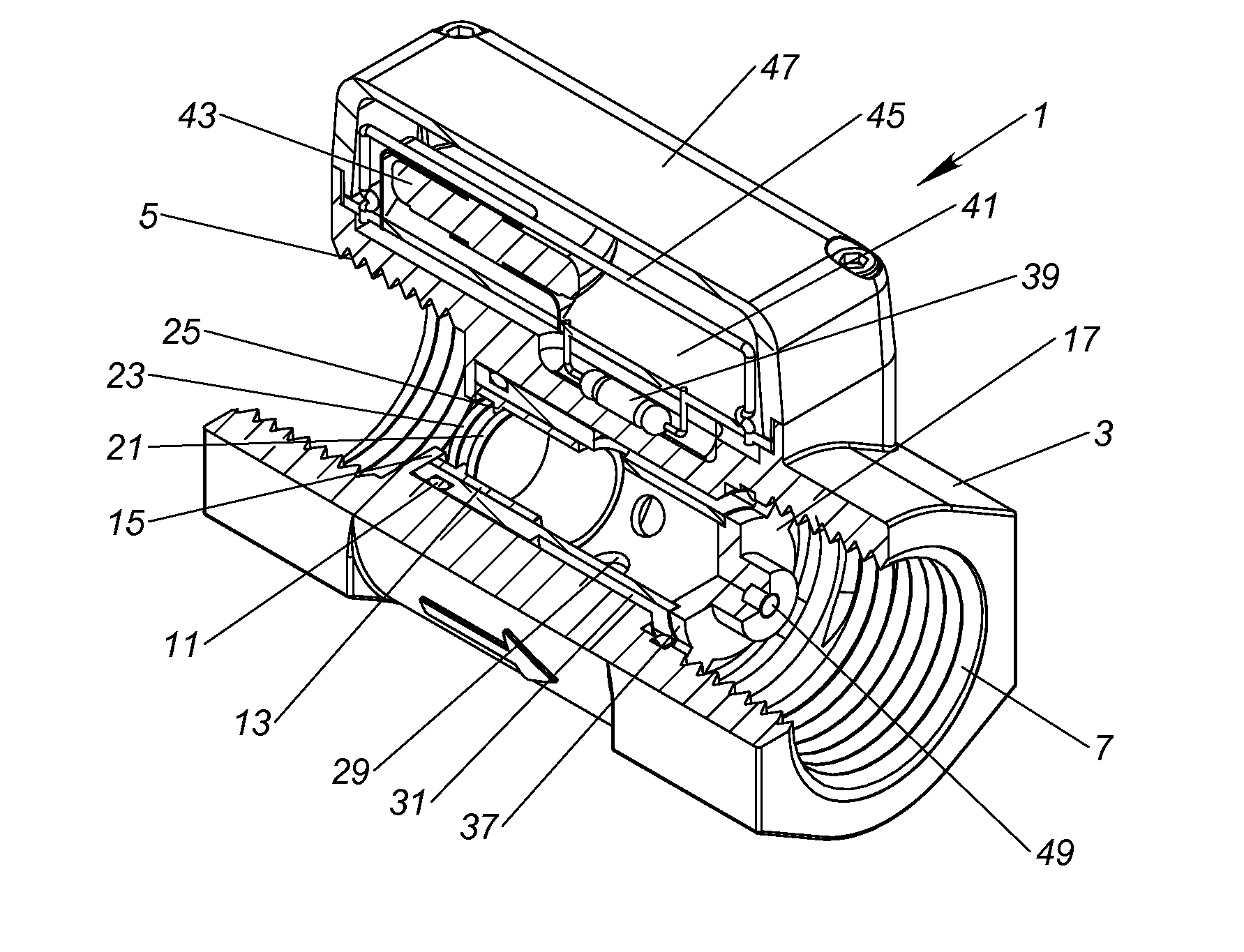
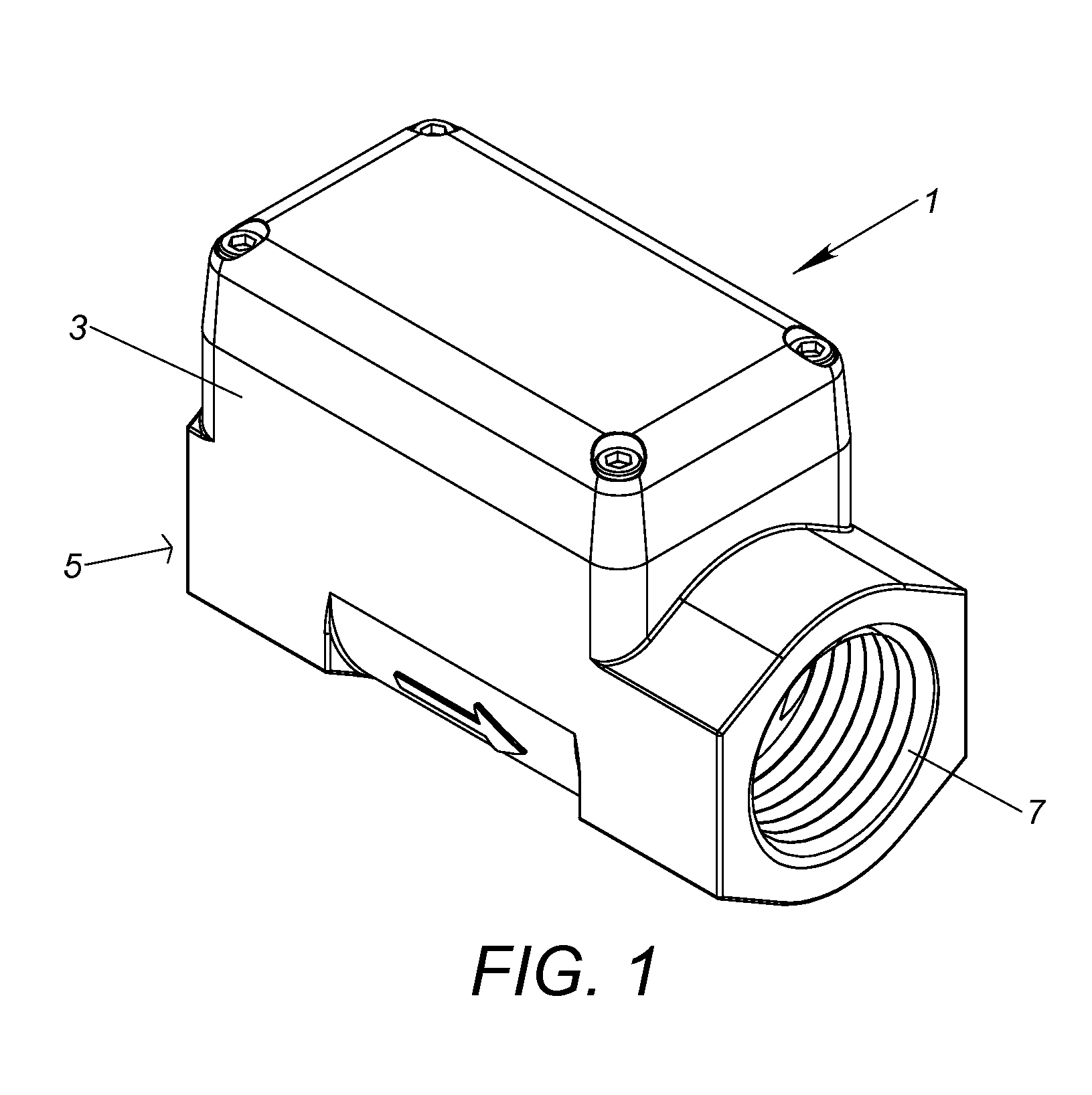
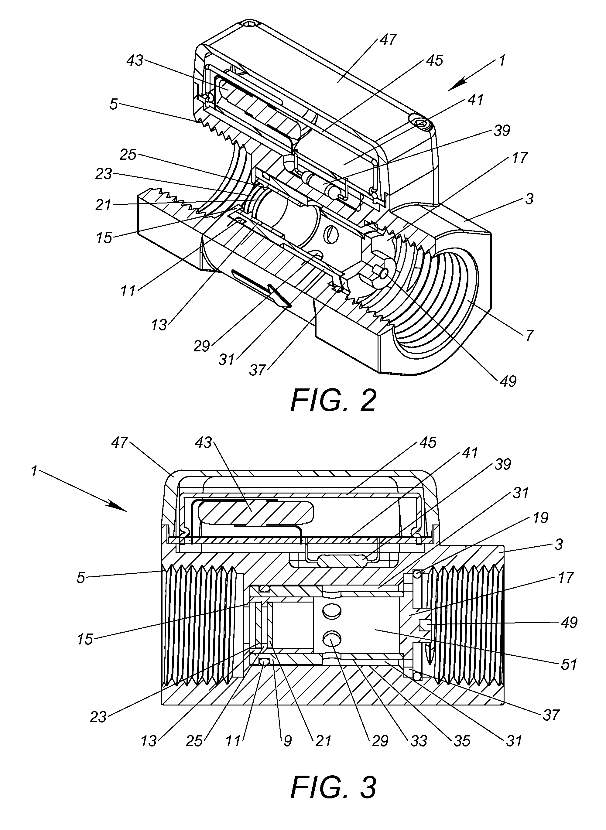
[0036]Shown in FIGS. 1 thru 5 is a fluid / gas flow switch 1 constructed in accordance with the present invention and configured for installation and use downstream of a typical gas grill appliance pressure regulator, or for use with household natural gas, where both the pressure and flow of gas is extremely low. The gas flow switch 1 includes an outer housing 3 with a threaded gas inlet port 5 and threaded outlet port 7. Gas flow switch 1 is therefore adapted to be threadably and sealably connected in vertical orientation (with inlet port 5 below the outlet port 7) inline with the gas line leading to the gas grill, downstream of the pressure regulator.

[0037]As shown in FIGS. 2 thru 5, the outer housing 3 includes an interior bore or chamber extending therethrough within which inner cylinder 9 is seated in sealed relation via o-ring 11. Inner cylinder 9 in turn carries piston 13 within its confines in close, free-floating slip-fit relation. Adjacent the inlet end of the flow switch 1,...


PUM


Abstract

A highly sensitive low loss and low flow fluid flow switch is coupled with an automatic timer and / or optional transmitter to indicate the flow of gas to an appliance and to automatically start a reminder timer to turn the appliance off. After a preset time limit has expired, the timer either sounds an alarm or wirelessly triggers an alarm in a remote location. The receiver portion of the wireless timer may be mounted directly to the appliance (grill handle), so that the timer automatically resets when activity (cover opening or closing) is detected, indicating the appliance is still in use. An alarm can also be configured to sound when the grill is attempted to be ignited with the cover closed, thereby avoiding a potential explosion. A biasing attraction magnet is incorporated in the fluid flow switch to offset either the force of gravity or a return spring in order to extend performance to low pressure and low flow applications. The piston is sealed for use in high pressure / low flow applications, and provided with a vent hole for residual gas bleed-off upon a stoppage of gas flow.

Description

CROSS REFERENCE TO RELATED APPLICATIONS[0001]This application is an application for a patent which is also disclosed in Provisional Application Ser. No. 61 / 009,725, filed on Dec. 29, 2007 by the same inventor, namely David A. Struyk, and entitled “GAS FLOW INDICATOR WITH AUTOMATIC ALARM TIMER,” the benefit of the filing date of which is hereby claimed.BACKGROUND OF INVENTION[0002]The present invention relates generally to the field of fluid flow indicators. More particularly, the present invention relates to a gas flow indicator which utilizes a highly sensitive gas flow switch in combination with a timer, alarm system and optional activity sensor for alerting the presence of sustained gas flow after a predetermined period of time.[0003]Gas-operated appliances, such as barbecue grills, deck heaters, fireplaces, and the like have become commonplace. The availability of either natural or propane gas as a fuel makes these appliances particularly convenient. However, it is commonplace f...

Claims


Application Information

Patent Timeline
Patent Type & Authority Applications(United States)
IPC IPC(8): F16K37/00
CPCH01H35/405G01P13/002Y10T137/8326
Inventor STRUYK, DAVID A.
Owner STRUYK DAVID
Why Eureka
Try Eureka