Toilet flush valve

a technology for flushing valves and toilets, applied in the field of flushing valves, can solve the problems of premature closing, no longer mandated minimum “hold down time”, and the effect of affecting the performance of such a valve body,

Inactive Publication Date: 2012-09-18
AS AMERICA
View PDF25 Cites 43 Cited by
  • Summary
  • Abstract
  • Description
  • Claims
  • Application Information

AI Technical Summary

Problems solved by technology

Although these prior solutions noted in the above-patents effectively remove waste from toilet bowls within government guidelines, such guidelines no longer mandate a minimum “hold down time”.
Problems are encountered when using such an elevated valve body having an optimal radiused inlet designed to enhance flow and maximize hydraulic energy through the valve body with a standard flapper-type valve cover.
A traditional flapper valve cover's performance used with such a valve body and a two-inch inlet becomes affected in terms of its ability to close when appropriate, sometimes closing prematurely, and in terms of its ability to re-open.
This problem can be exacerbated in a radiused inlet valve body design, because the extension of the inlet opening due to the presence of the radius, which is optimized for high-efficiency flow through the valve body, can require an even larger sized flapper to cover the opening created by the radius thereby contributing to the buoyancy issues affecting opening and closing of the flapper cover.
These factors combine to make it difficult to properly open and close a standard flapper on a valve assembly configured for use in an HPT or, preferably an HET and having an elevated valve body and radiused inlet, even in comparison to standard low profile, non-elevated flush valve bodies having standard flapper-type valve covers, for example, a commercially available Fluidmaster® Flush Valve Model 507.
Another problem encountered in prior art flush valve designs is when such flush valves, whether suitable for high-efficiency toilets or not, are optimized for flow design, but have outlets which, when installed introduce fluid flow directly into an inlet chamber of a toilet bowl having a lower floor which lies in a plane perpendicular to the flow coming out of the flush valve outlet.
The impact of the contact between the high flow rate through the valve caused by flushing against the floor of the inlet chamber of the toilet bowl introduces undesirable turbulence which reduces the hydraulic energy available from the water exiting the outlet of the flush valve.

Method used


Image

  • Toilet flush valve
  • Toilet flush valve
  • Toilet flush valve

Examples


example

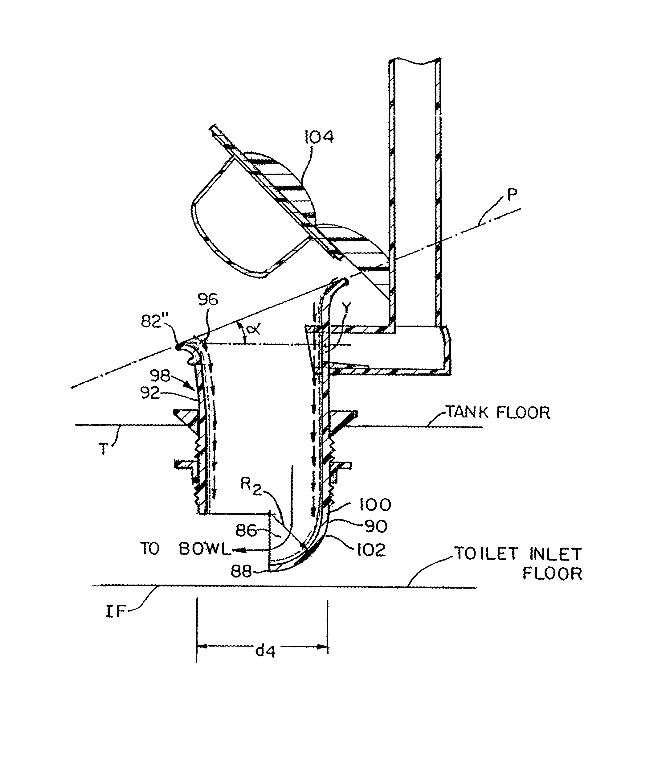
[0081]A series of valve bodies were prepared by interchanging inlet sections so as to have a radiused inlet or no radiused inlet, to have tapered and non-tapered extension sections as well as tapered and non-tapered base sections. The flow properties were compared to flow properties through a standard commercially available 2-inch Fluidmaster® 507 valve having a low profile and a straight bore flow profile, operating with a flapper valve cover at optimal flush volumes for such a valve (Comparative Standard Sample CE). The results of the varying sample valve bodies combined with varying flapper valve covers of differing buoyancy levels show the impact of a radiused inlet as being beneficial, as well as the benefit of including at least one tapered section therein, and most preferably including such features with a sufficiently buoyant flapper valve cover capable of having a buoyant force equivalent to the force necessary to displacing about 70 grams of water with air, provided signif...


PUM


Abstract

Flush valve assemblies are provided that include a valve body which may have a radiused inlet portion, an upper inlet end having an inlet opening, a lower outlet end having an outlet opening, and a wall extending between the upper inlet end and the lower outlet end and having an interior surface defining a flow path that extends generally longitudinally through the valve body from the inlet opening to the outlet opening and that has a generally circular transverse cross-section. A height measured longitudinally through the valve body is greater than a largest diameter of the transverse cross-section of the flow path so as to enable the valve bodies herein to have an elevated wall and head from a toilet tank floor. The assemblies may include a flapper valve cover detachably connected to the flush valve assembly and having a transverse cross-sectional diameter sufficiently large to cover the inlet opening of the valve body, a pivot mechanism and a flapper bulb. The flapper valve cover is sufficiently buoyant so as to be capable of resisting the force of flowing water and remain open so as to allow flush water to pass through the valve body when the valve body is installed on a toilet having a flush volume of about 1.6 gallons per flush or less before closing the valve cover so as to be useful in high performance, and also in high-efficiency toilets.

Description

CROSS-REFERENCE TO RELATED APPLICATIONS[0001]This application claims the benefit under 35 U.S.C.§119(e) of U.S. Provisional Patent Application No. 61 / 072,969, filed Apr. 4, 2008, the entire disclosure of which is incorporated herein by reference.BACKGROUND OF THE INVENTION[0002]1. Field of the Invention[0003]The present invention relates to plumbing in a water closet or toilet water tank of a toilet, and more particularly to a flush valve for use in the water tank of a toilet assembly.[0004]2. Description of Related Art[0005]Toilets and toilet assemblies for removing waste products are well known. Typically, toilets incorporate three systems that work together to perform the flushing action. Those systems are (1) the bowl siphon, (2) the flush mechanism, and (3) the refill mechanism. Working in concert, these three systems enable the flushing function of the toilet.[0006]Usually, the toilet tank, positioned over the back of the toilet bowl in the toilet assembly, holds water that is...

Claims


Application Information

Patent Timeline
Patent Type & Authority Patents(United States)
IPC IPC(8): E03D1/34
CPCE03D1/306
Inventor JENSEN, ROBERT M.
Owner AS AMERICA
Why Eureka
Try Eureka