
Flute

a technology for flutes and instruments, applied in the field of flutes, can solve the problems of affecting the results of practice and learning, affecting the timbre of flutes, neck and spine tension and stiffness, etc., and achieves the effects of reducing the difficulty of playing the flute, and improving the sound quality

Active Publication Date: 2012-09-25
GISLER BARBARA +1
View PDF13 Cites 2 Cited by
  • Summary
  • Abstract
  • Description
  • Claims
  • Application Information

AI Technical Summary

Problems solved by technology

Also, adult-figured flute players do not have to put they heads in an unnatural position, which could cause fatigue.
However, for flute players without adult figures, especially children, the interval between the mouthpiece plate and the keys activated to change the pitch during blowing the flute are too large and cause various defects.
The gesture over expanding the arms hinds the dexterity of fingers and easily causes tension and stiffness of shoulders and spine, which affects the results of practice and learning and damages the bones.
However, the aforementioned suggestion deviates the mouthpiece plate from a geometric axis of the body tube that are mounted with keys, so that a flute player cannot stably hold the flute and cannot study the timbre of the flute.
Also, specific fingerings learned by operating the bent flute are useless when the flute player is playing a conventional flute with a linear mouthpiece tube.
Furthermore, it is difficult for the player familiar with the bent flute to adapt himself / herself to fingerings of a conventional flute with a linear mouthpiece tube.

Method used


Image

  • Flute
  • Flute
  • Flute

Examples


first embodiment

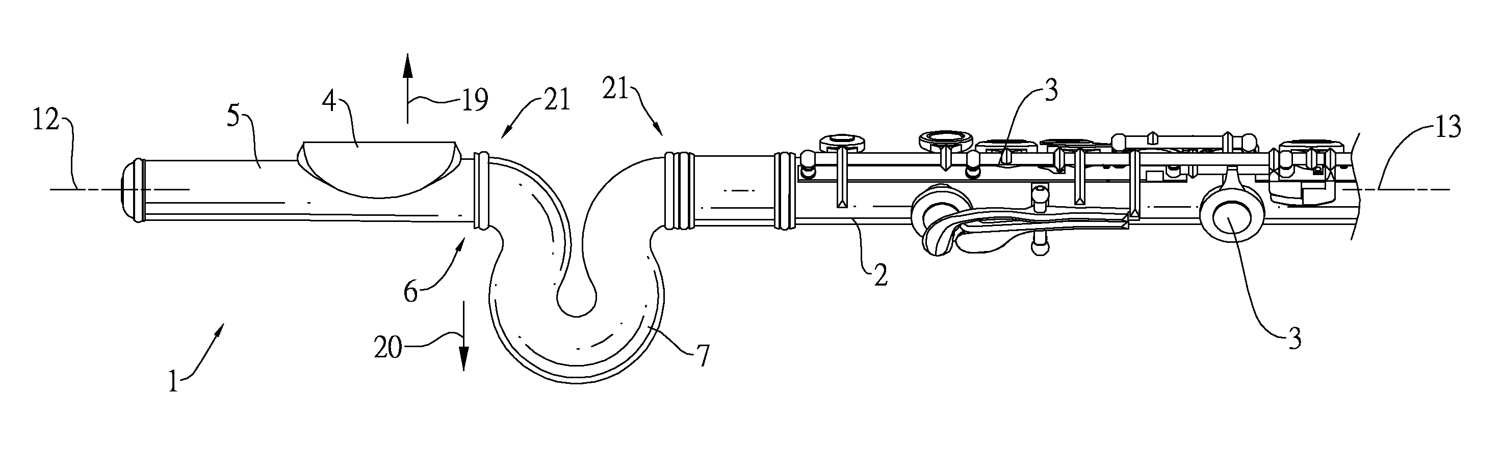
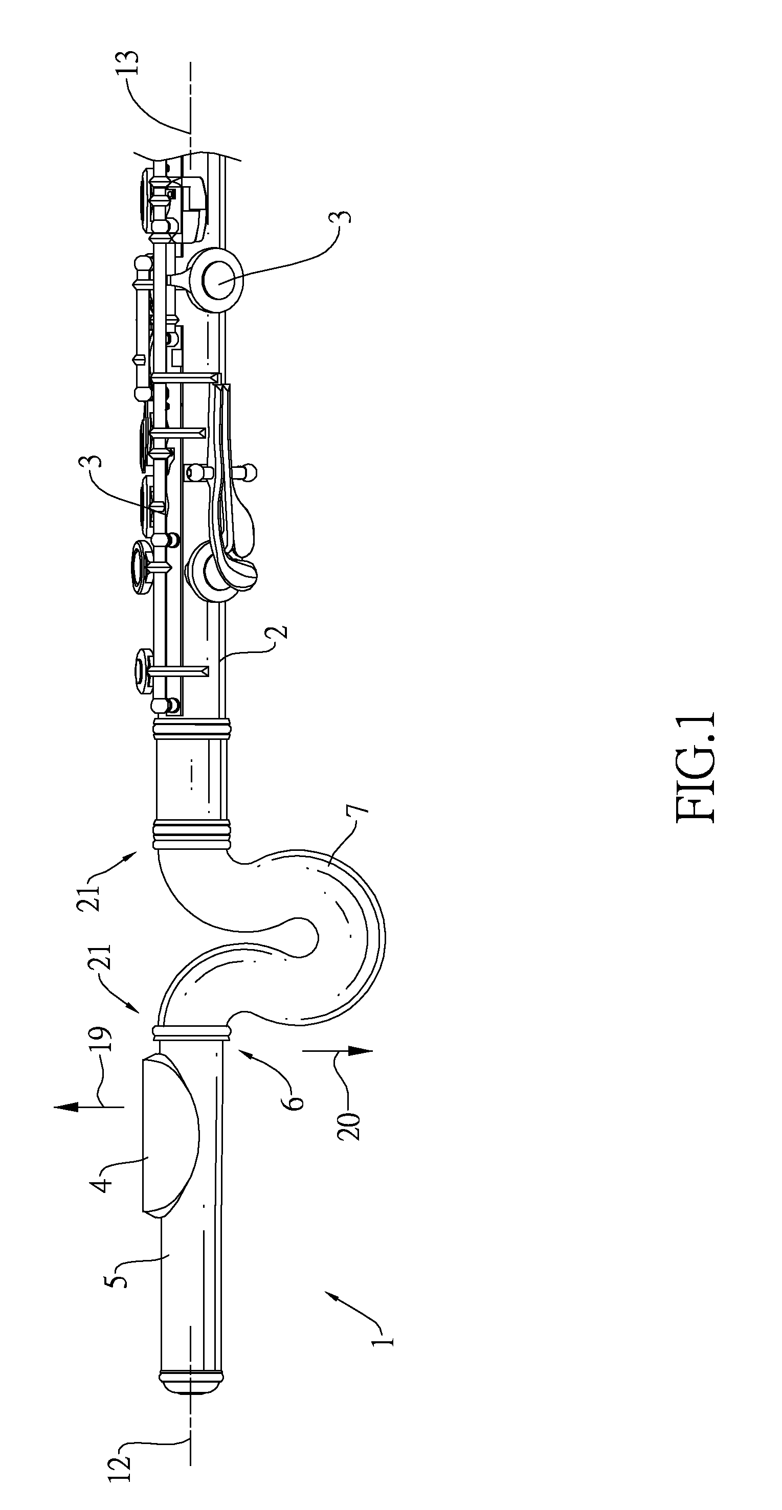
[0014]With reference to FIGS. 1 and 2, a flute in accordance with the present invention comprises a pipe.

[0015]The pipe has a body tube (2), a mouthpiece tube (5) and a curved tube (7).

[0016]The body tube (2) is linear and has multiple keys (3) mounted on the body tube (2) for changing the pitch of the flute.

[0017]The mouthpiece tube (5) is linear and is connected to the body tube (2) and has an outside end, an inside end and a mouthpiece plate (4). The inside end is defined opposite to the outside end and protrudes toward the body tube (2). The mouthpiece plate (4) is mounted on the mouthpiece tube (5).

[0018]The curved tube (7) is mounted on the inside end of the mouthpiece tube (5) and has a first end (11) and a second end (9). The first end (11) defines and has a first geometric axis (10) along which the curved tube (7) extends. The second end defines and has a second geometric axis (8) along which the curved tube (7) extends. The first and second geometric axes (10, 8) are align...

second embodiment

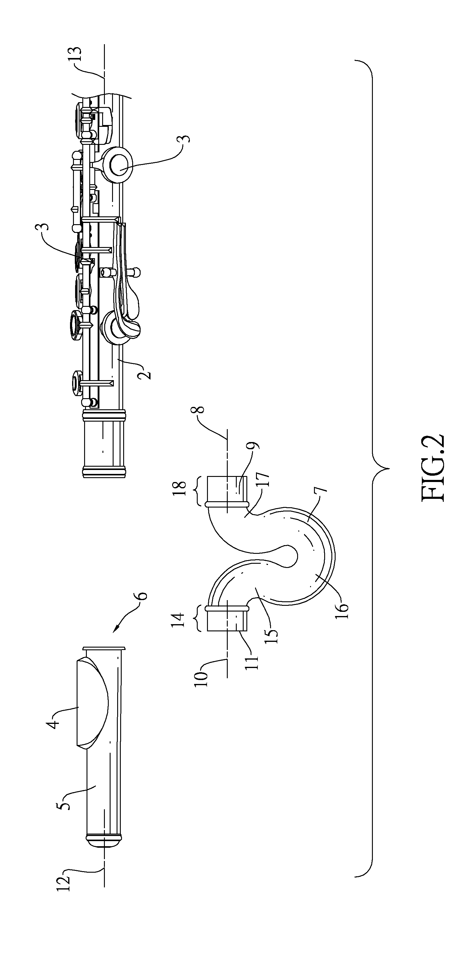
[0023]In the second embodiment as shown in FIGS. 3 and 4, the curved tube (7) is U-shaped. The curved tube (7) with such configuration may be manufactured easily. The size of the U-shaped curved tube (7) may be changed in a size range to vary the interval between the mouthpiece plate (4) and the keys (3). The curved tube (7) has a first curved section (15), a reverse curved section (16) and a second curved section (17). The first curved section (15) is formed on the first section (14) and extends outward from the first geometric axis (10). The reversely curved section (16) is formed on the first curved section (15). The second curved section (17) is formed on the reversely curved section (16) and is symmetrical to the first curved section (17) and extends toward the second section (18). The extension of the second section (18) is defined by the second geometric axis (8).

[0024]In the first and second embodiments as shown in FIGS. 1 to 4, the first and second sections (14, 18) of the ...


PUM


Abstract

A flute has a pipe. The pipe has a linear body tube and a linear mouthpiece tube. The body tube has multiple keys for changing the pitch of the flute. The mouthpiece tube is connected to the body tube and has a mouthpiece plate. A curved tube is mounted on one end of the mouthpiece tube facing the body tube. The curved tube, mouthpiece tube and body tube are aligned with one another.

Description

BACKGROUND OF THE INVENTION[0001]1. Field of the Invention[0002]The present invention relates to a flute, and more particularly to a flute that has a linear body tube and a mouthpiece tube. The linear body tube has multiple keys for changing the pitch. The mouthpiece tube has a mouthpiece plate and is connected to the linear body tube having the keys.[0003]2. Description of Related Art[0004]A conventional flute has a mouthpiece tube directly connected to a body tube mounted with keys. Because the pitch performed by the flute must be limited and defined in a precise frequency range, an interval between a mouthpiece plate and keys activated during blowing the flute need to be sufficiently large. For flute players with adult figures, they can adjust their arms to an optimal gesture to correspond to the interval between the mouthpiece plate and the keys and comfortably operate the flute. They do not need to employ a gesture that obstructs the operation of fingers and causes tiredness wh...

Claims


Application Information

Patent Timeline
Patent Type & Authority Patents(United States)
IPC IPC(8): G10D7/02
CPCG10D7/026
Inventor GISLER, BARBARATOMASI, WERNER
Owner GISLER BARBARA
Learn More