Paint roller sleeve storage container

a paint roller and storage container technology, applied in the field of paint roller sleeve storage containers, can solve the problem of requiring one coat of pain

Inactive Publication Date: 2010-11-02
OBVIOUS SOLUTIONS
View PDF3 Cites 61 Cited by
  • Summary
  • Abstract
  • Description
  • Claims
  • Application Information

AI Technical Summary

Benefits of technology

[0003]The object of this invention is to provide a container for a just used paint roller sleeve in which it can be stored and kept in such a condition that be used again immediately, for the same color paint, without first being cleaned. An additional object of this invention is to provide means for removing a wet paint sleeve from the roller without the painter's hand, whether gloved or otherwise, coming into direct contact with the sleeve.
[0004]In accordance with the present invention, there is provided an improved storage container which comprises a generally cylindrical tubular structure having a thin wall made of a flexible, resilient plastic and at least one pleated wall section joined thereto. Formed of a hinged-type plastic, the pleated wall section can be pressed inwardly by hand. When the pleated wall section is so pressed, teeth-like projections on its inside surface are brought into contact with any paint roller sleeve housed temporarily within the storage container and can be used to grip the sleeve firmly.
[0007]Longitudinal ribs which extend inwardly from the inner walls of the tubular structure help to center the sleeve within the container and keep the sleeve, regardless of thickness of its nap from rattling around in the container The ribs are rounded off at proximate with the opening in the tubular structure so as to help guide the sleeve into the container.

Problems solved by technology

Further, in many jobs more than one coat of paint is required.

Method used


Image

  • Paint roller sleeve storage container
  • Paint roller sleeve storage container
  • Paint roller sleeve storage container

Examples


Embodiment Construction

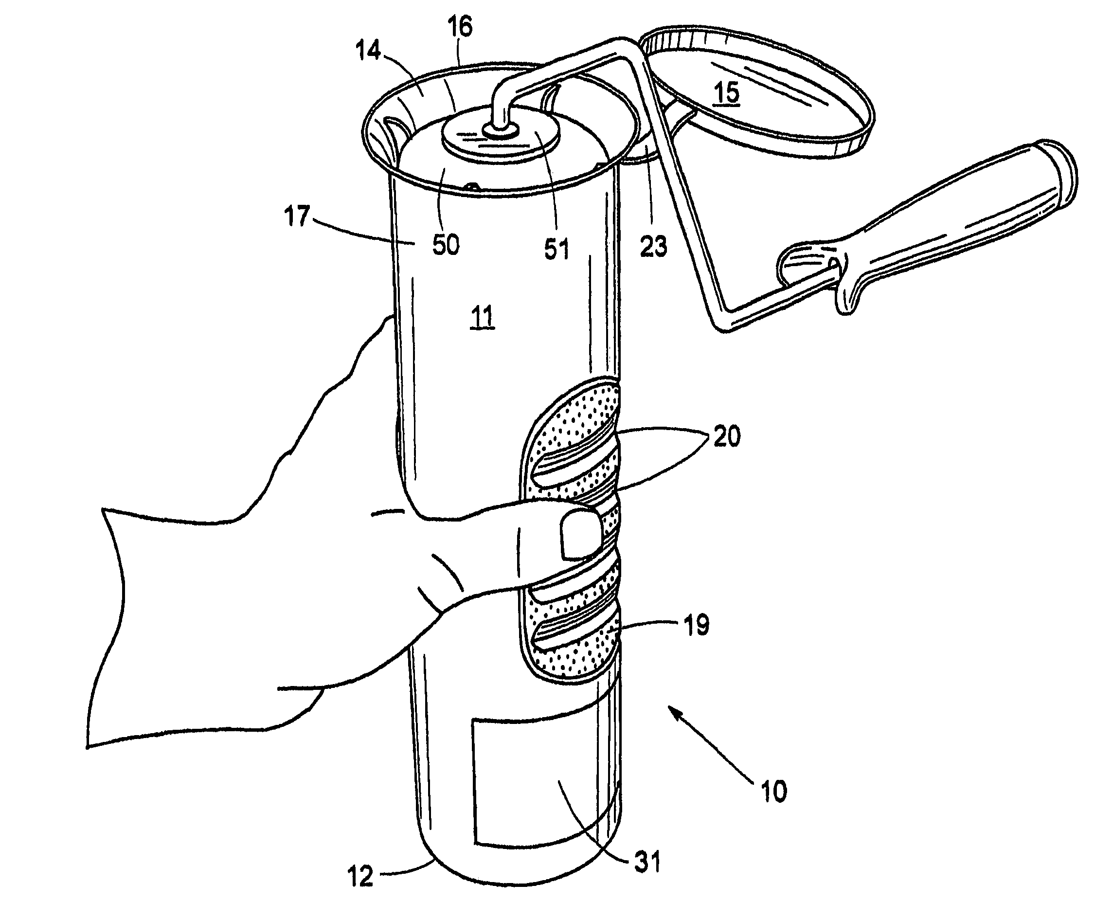
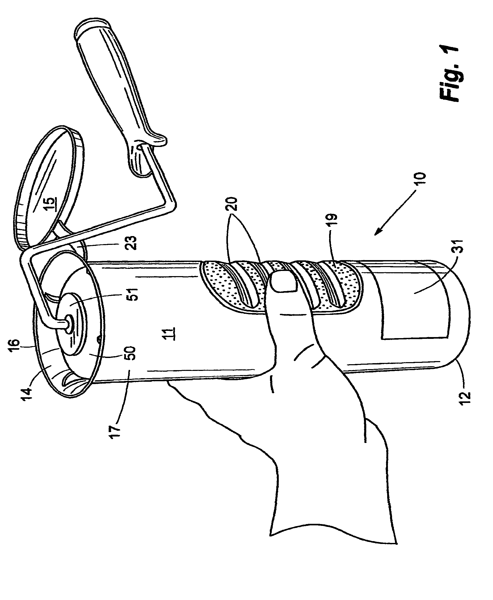
[0018]Referring to the drawings, a storage container 10 for a paint roller sleeve 50 includes a flexible, resilient, generally cylindrical housing 11 for removably storing the sleeve 50 therein. Sealed on its lower end 12, the housing 11 defines an upper opening 13, which is surrounded by a rim 16 atop sidewall 14. Terminating with the rim 16, the sidewall 14 tapers outwardly to form a funnel that aids in the insertion of the sleeve 50 while it is mounted on the paint roller 51 and keeps paint from dripping outside the container 10.

[0019]In the preferred embodiment, a cap 15 snap-fits on the rim 16 to provide an airtight seal. Attached to the cap 15 and to the housing 11 is a strap 23. When the container 10 is closed, the cap-retaining strap 23 is long enough to form a loop that can be used for hanging the container 10 on a pegboard or equivalent for display (FIGS. 2 and 3).

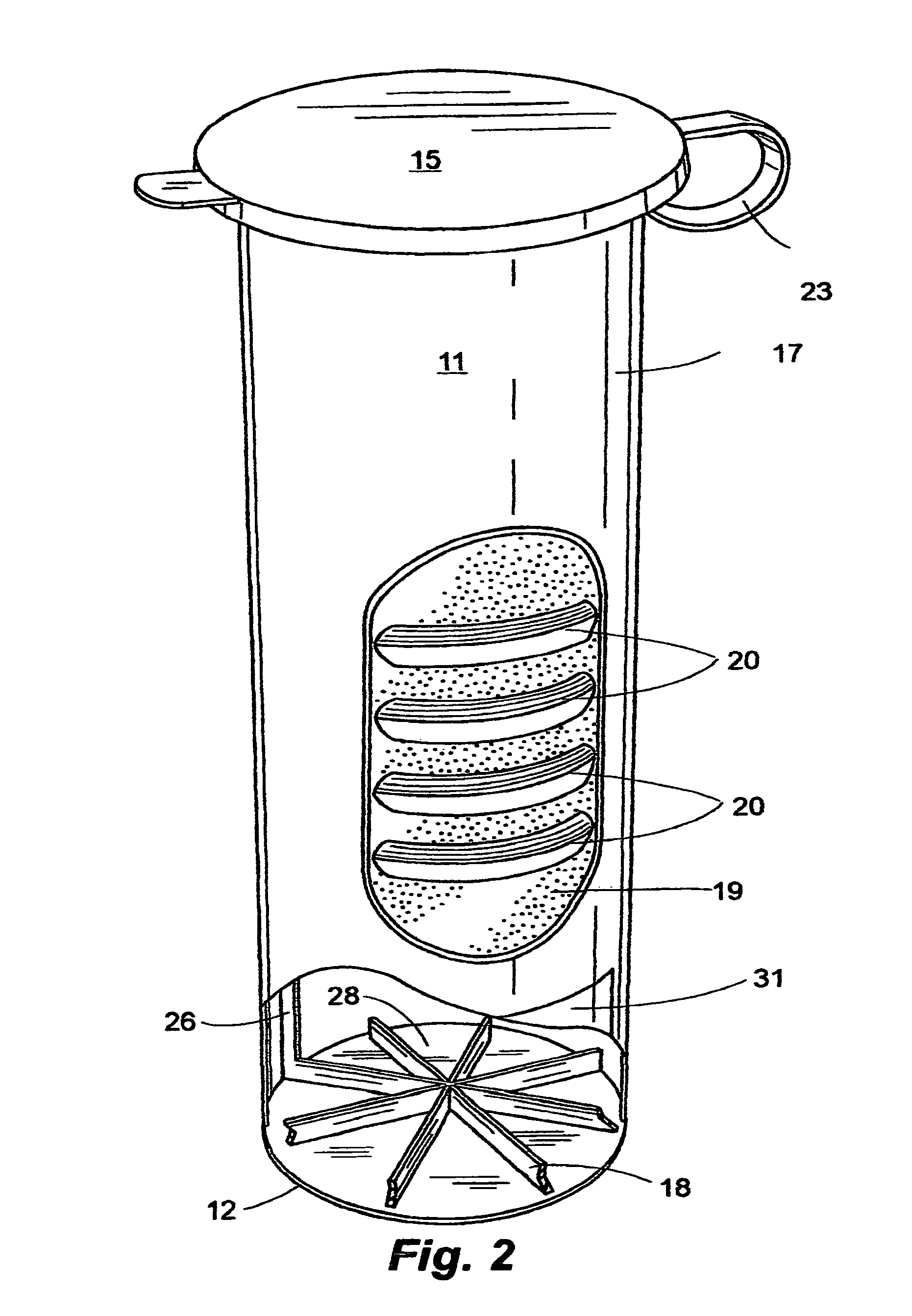
[0020]As illustrated in FIG. 2, the container 10 preferably includes a standoff 18 disposed within the housing...


PUM


Abstract

A storage container for paint roller sleeve includes a set of flutes on at least two opposing sides of an interior surface of said cylinder for stabilizing a roller cover in place from rattling inside of the housing and for holding said roller cover in place when extracting a roller frame from said roller cover. Each set of flutes includes three interior flutes that located between said two exterior flutes. The interior flutes include a middle flute that is set back a distance from the other two interior flutes so that when the exterior surface of the container is pressed inward said middle interior flute cuts into a paint roller sleeve housed within the container and the other two interior flutes bend outward around a nap of said roller sleeve to better hold said roller sleeve in place when a roller frame is being extracted from said roller sleeve.

Description

RELATED APPLICATIONS[0001]This non-provisional application is a Continuation-in-Part of U.S. application Ser. No. 11 / 472,092 by Mowe, et al. filed Jun. 21, 2006 (abandoned) and provisional application Ser. No. 61 / 203,622 by Mowe, et al. filed Dec. 24, 2008.BACKGROUND OF THE INVENTION[0002]During a standard workday a painter may use one or more paint roller sleeves. Further, in many jobs more than one coat of paint is required. Moreover, if the job is not finished prior to a lunch break or at the end of the Workday, the sleeve must be cleaned or discarded. There is a need for a device in which a freshly used, yet to be cleaned paint roller sleeve can be stored overnight, ready for reuse the next day.SUMMARY OF THE INVENTION[0003]The object of this invention is to provide a container for a just used paint roller sleeve in which it can be stored and kept in such a condition that be used again immediately, for the same color paint, without first being cleaned. An additional object of th...

Claims


Application Information

Patent Timeline
Patent Type & Authority Patents(United States)
IPC IPC(8): B65D85/00B65D53/00
CPCB44D3/125B65D81/261
Inventor MOWE, WILLIAM B.MOWE, KELLY L.
Owner OBVIOUS SOLUTIONS
Why Eureka
Try Eureka