Footwear sole with a stiffness adjustment mechanism

a technology of stiffness adjustment and sole, applied in the field of footwear sole, can solve the problems of increasing the thickness of the midsole, the source of foot and leg injury, and the tendency to overpronation, so as to facilitate the movement of the band and alter the deflection and stiffness characteristics

Inactive Publication Date: 2005-02-08
NIKE INC
View PDF2 Cites 112 Cited by
  • Summary
  • Abstract
  • Description
  • Claims
  • Application Information

AI Technical Summary

Benefits of technology

[0014]The present invention is an article of footwear that includes an upper for receiving a foot of a wearer and a sole attached to the upper. The sole incorporates at least one support element that includes an exterior surface, at l

Problems solved by technology

Other prior art midsoles utilize fluid or gas-filled bladders of the type disclosed in U.S. Pat. Nos. 4,183,156 and 4,219,945 to Marion F. Rudy. Although foam materials succeed in providing cushioning for the foot, foam materials also impart instability that increases in proportion to midsole thickness.
Pronation, the inward roll of the foot while in contact with the ground, although normal, can be a potential source of foot and leg injury, particularly if it is excessive.
The use of soft cushioning materials in the midsole of running shoes, while providing protection against impact forces, can encourage instability of the sub-talar joint of the ankle, thereby contributing to the tendency for over-pronation.
This instability has been cited as a contributor to “runners knee” and other athletic injuries.
While making such movements, footwear instability may lead to excessive inversion or eversion

Method used


Image

  • Footwear sole with a stiffness adjustment mechanism
  • Footwear sole with a stiffness adjustment mechanism
  • Footwear sole with a stiffness adjustment mechanism

Examples


second embodiment

[0045]FIG. 21A is a perspective view of a second article of footwear including columns according to the present invention.

[0046]FIG. 21B is a perspective view of a stability component according to the second embodiment of the present invention.

[0047]FIG. 21C is a second perspective view of the stability component of 21B.

[0048]FIG. 21D is a top plan view of the stability component of 21B.

[0049]FIG. 22 is a side view of an alternate column configuration that each include a band.

[0050]FIGS. 23A-23D are side views of columns having two bands and no band indentations.

[0051]FIGS. 24A-24D are side views of columns having two bands and three band indentations.

[0052]FIG. 25 is a perspective view of an article of footwear including columns according to the second embodiment of the present invention.

DETAILED DESCRIPTION OF THE INVENTION

[0053]Referring to the FIGS. 3-25, wherein like numerals indicate like elements, articles of footwear in accordance with the present invention are illustrated. ...

first embodiment

[0054]The present invention is applicable to a wide variety of footwear having support elements disposed in the sole. Depending upon the primary use for the footwear, the support elements may include either a flat or canted upper surface. For general information relating to footwear having support elements with a flat upper surface, see U.S. Pat. Nos. 5,353,523 and 5,343,639 to Kilgore et al., incorporated by reference. For general information relating to footwear having a canted upper surface see the detailed discussion concerning the first embodiment, included herein.

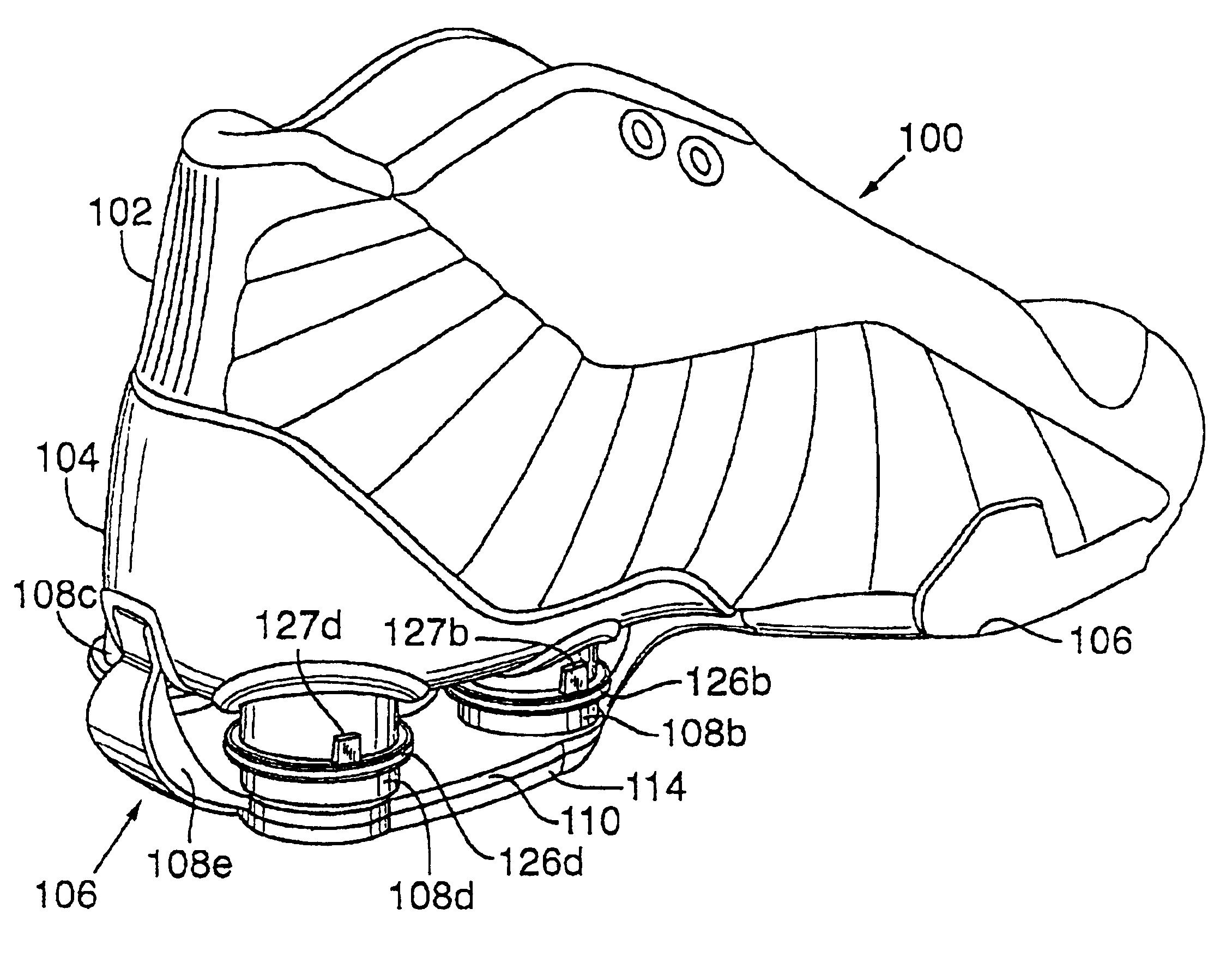
[0055]Support elements in accordance with a first embodiment of the present invention are disclosed in FIGS. 3-19. Shoe 100 includes three primary components: upper 102, heel plate 104, and sole 106. Sole 106 is further comprised of support elements 108, including columns 108a-108d and aft support 108e, base 110, base plate 112 (not visible), and outsole 114. Upper 102 is attached to heel plate 104 in the aft portion ...


PUM

PropertyMeasurementUnit
Lengthaaaaaaaaaa
Stiffnessaaaaaaaaaa

Abstract

The invention is an article of footwear having a sole comprised of one or more support elements formed of a resilient, compressible material. The support elements are designed such that the positions of one or more bands that encircle the exterior surface of the support elements may be altered such that the deflection characteristics of the support elements are changed. In order to facilitate the repositioning of the bands, the support element includes an access indentation defined by the exterior surface or flanges that are secured to each band.

Description

BACKGROUND OF THE INVENTION[0002]1. Field of the Invention[0003]The present invention relates to footwear. The invention concerns, more particularly, a sole for footwear that includes a mechanism for adjusting stiffness characteristics of the sole.[0004]2. Description of Background Art[0005]Sole design for modern athletic footwear is generally characterized by a multi-layer construction that includes an outsole, midsole, and insole. The midsole typically includes a soft, foam material to attenuate impact forces and absorb energy when the footwear contacts the ground during athletic activities. Other prior art midsoles utilize fluid or gas-filled bladders of the type disclosed in U.S. Pat. Nos. 4,183,156 and 4,219,945 to Marion F. Rudy. Although foam materials succeed in providing cushioning for the foot, foam materials also impart instability that increases in proportion to midsole thickness. For this reason, footwear design often involves a balance of cushioning and stability.[0006...

Claims


Application Information

Patent Timeline
IPC IPC(8): A43B7/14A43B13/18A43B13/20
CPCA43B7/1465A43B13/20A43B13/189A43B13/181A43B7/1464A43B7/1469
Inventor AVENI, MICHAEL A.GRELEWICZ, DAVID
Owner NIKE INC
Why Eureka
Try Eureka