Fracture brace

a brace and fracture technology, applied in the field of fracture braces, can solve the problems of affecting the inability to adjust the normal position of the limb, and the discomfort of patients, etc., and achieve the effect of preventing the flexion of the injured wris

Active Publication Date: 2007-05-03
DJO
View PDF50 Cites 57 Cited by
  • Summary
  • Abstract
  • Description
  • Claims
  • Application Information

AI Technical Summary

Problems solved by technology

Certain injuries, particularly limb fractures, result in the limb becoming misaligned with respect to its normal position.
Such braces, although generally effective, cause discomfort and other problems for the patient.
This compression may be applied too tightly for some patients; it also may become too loosely attached over time as swelling in the arm recedes.

Method used


Image

  • Fracture brace
  • Fracture brace
  • Fracture brace

Examples


Embodiment Construction

[0029] The device and methods described herein provide for braces and methods for bracing an injured limb. To provide an overall understanding of the invention, certain illustrative embodiments are herein described, as more particularly set forth in the figures. However, the systems and methods described herein can be adapted and modified for other suitable applications, and that such other additions and modifications will not depart from the scope hereof.

[0030] For example, representative embodiments may be applied to injuries to the forearm, the wrist, hand, fingers, the upper arm, injuries to the leg, or ankle, or to bones of any or all of the foregoing.

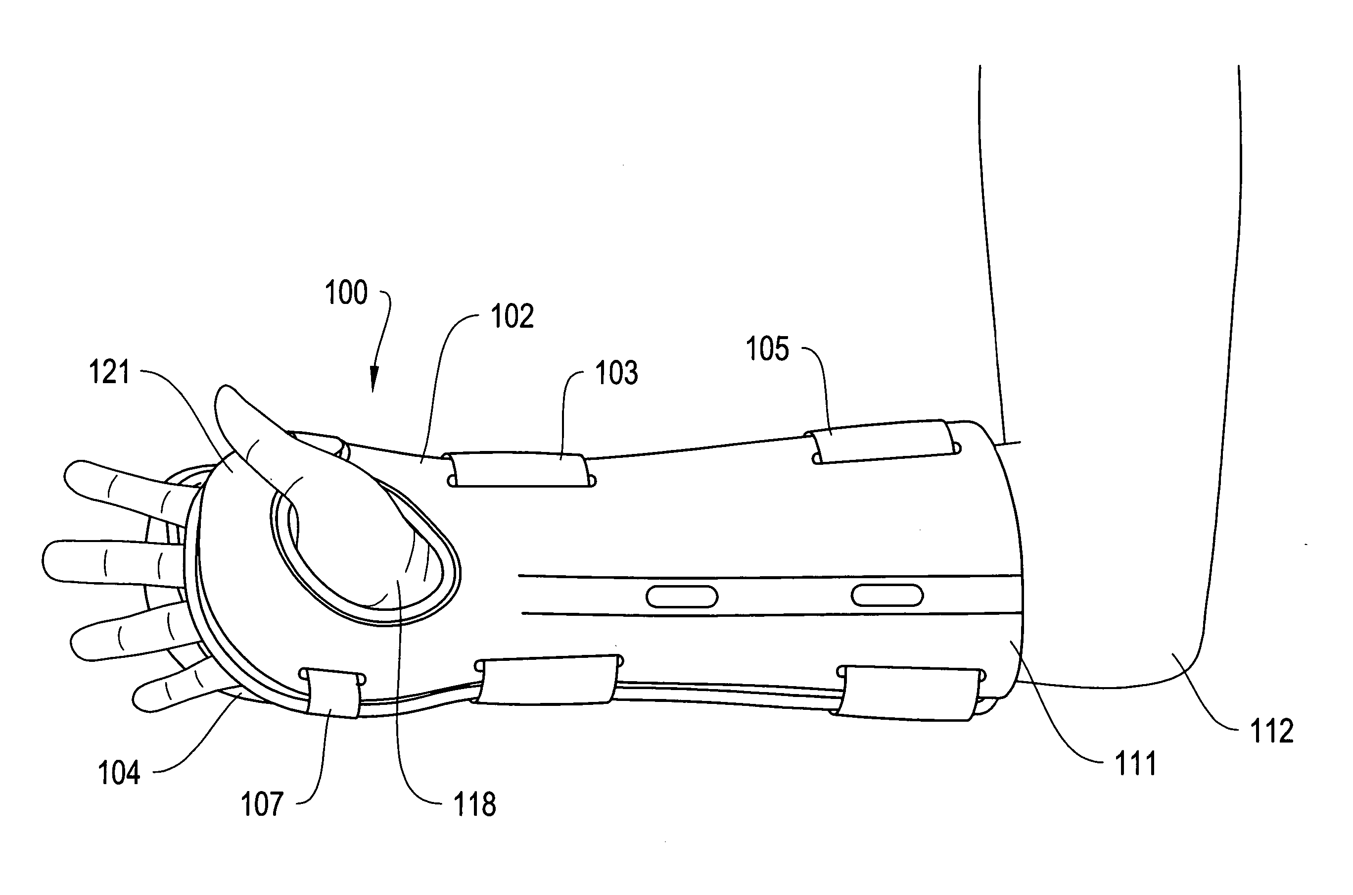
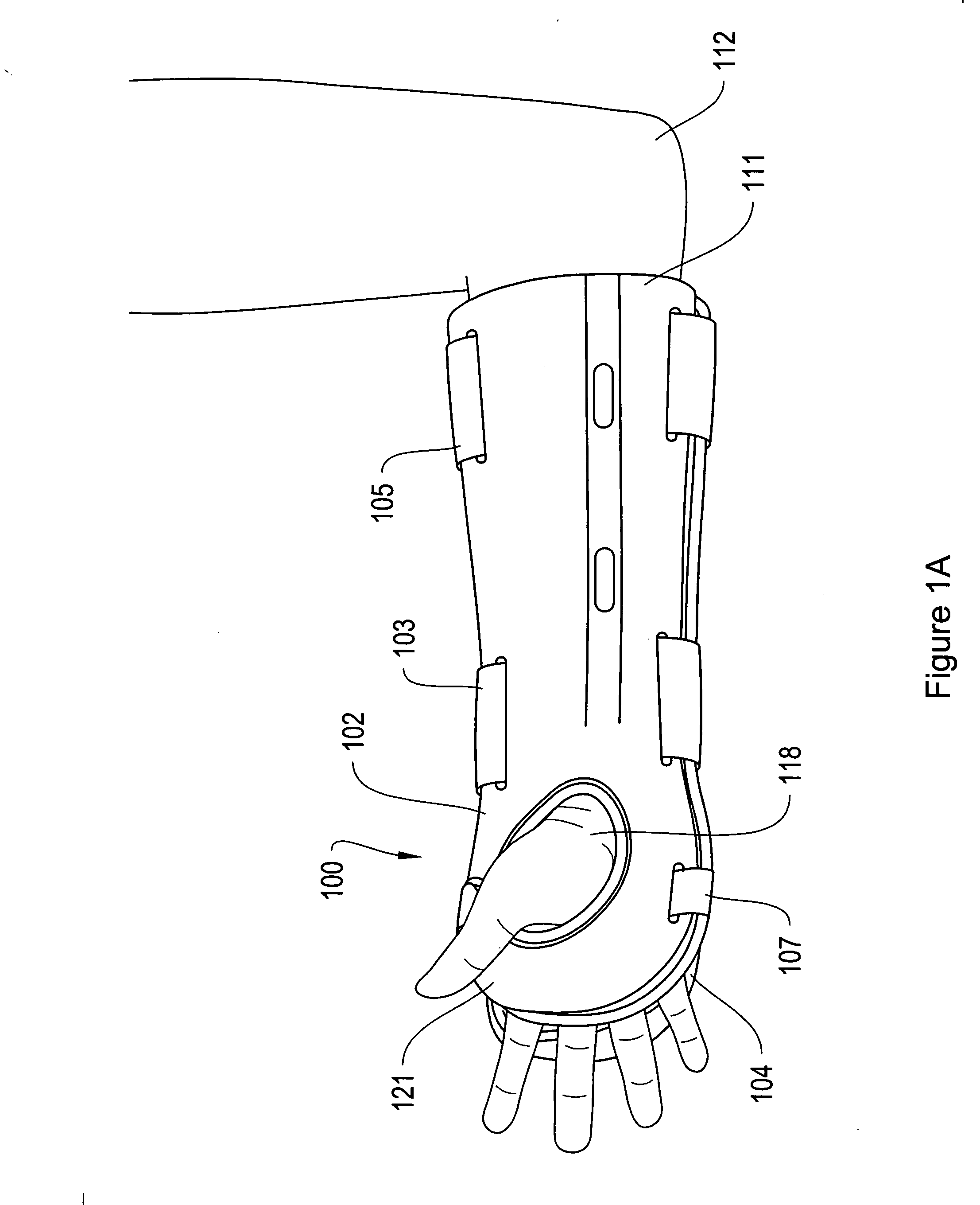
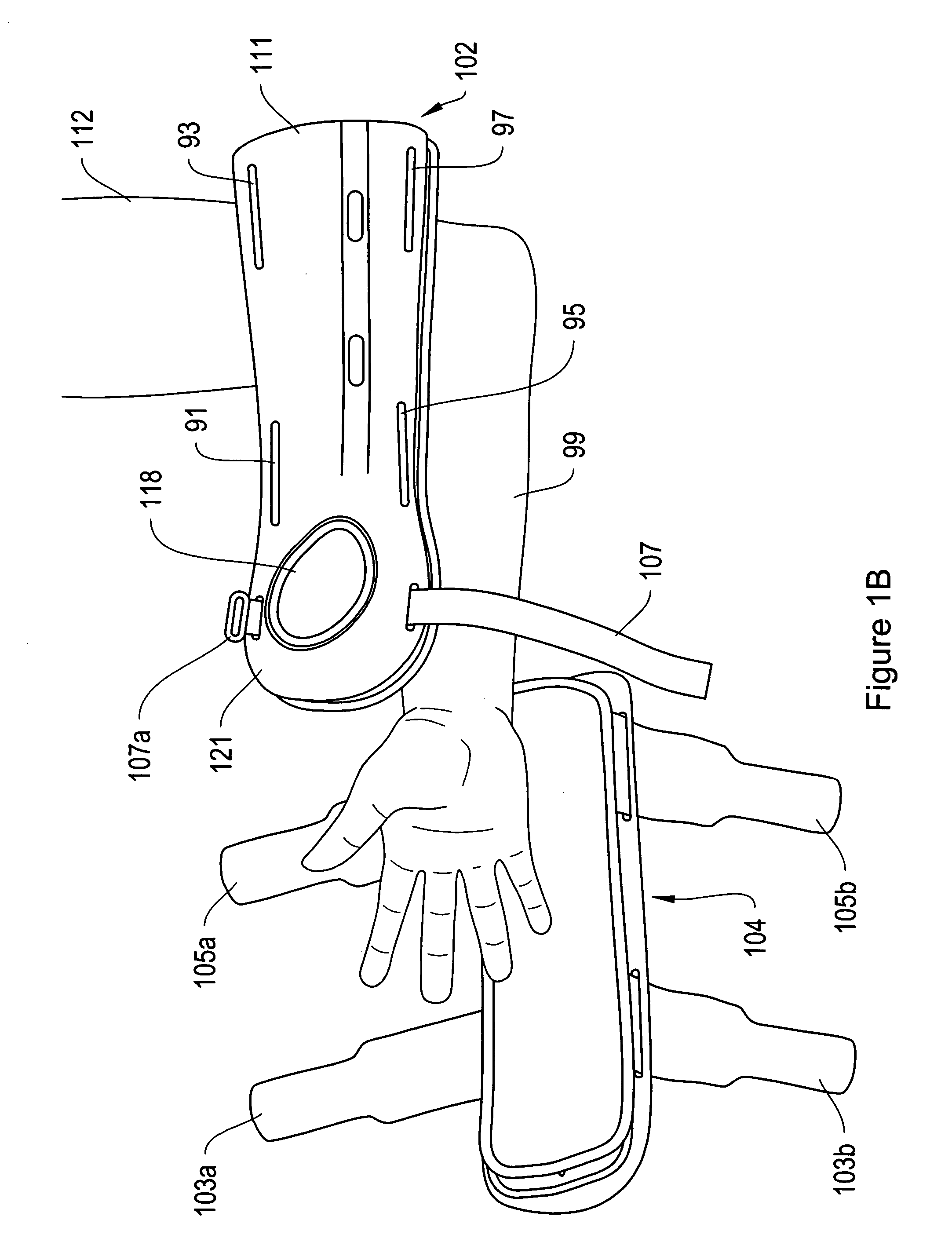
[0031]FIGS. 1A-1B depict an embodiment of a brace 100, including a casing 111 having medial 102 and lateral 104 components, the brace 100 being fitted to a patient's limb 112 with medial portion 102 fitted to the volar side 99 of the user's arm and wrist and the lateral portion 104 fitted to the dorsal side (the reverse side of ...


PUM


Abstract

The invention provides, in various embodiments, braces that are capable of stabilizing an injured limb, particularly an injured wrist. An exemplary brace fits across the injury in contact with the user's limb and has an adjustable casing and compressible material.

Description

RELATED APPLICATIONS [0001] This application is related to U.S. patent application Ser. No. 11 / 051791, filed Feb. 3, 2005, the specification of which is incorporated by reference herein.BACKGROUND [0002] Injuries to the limbs, particularly fractures of the hands, arms and wrist, are commonly treated by the use of a cast or other brace that supports the injured limb and, in certain cases, prevents the limb from rotating around the wrist or other applicable joint. These injuries include sprains, fractures, contusions and other injuries that are common and frequent and, unless properly treated, recurrent. [0003] Certain injuries, particularly limb fractures, result in the limb becoming misaligned with respect to its normal position. This effect may be seen, for example, in an open wrist fracture where radial bones puncture and protrude through the skin and result in the broken radius becoming further bent or otherwise deformed. To treat such a fracture, the physician must appropriately...

Claims


Application Information

Patent Timeline
Patent Type & Authority Applications(United States)
IPC IPC(8): A61F5/00
CPCA61F5/0118A61H2201/1697A61F5/012
Inventor HARGRAVE, DAVID C.PRAIS, EUGENE
Owner DJO
Why Eureka
Try Eureka