Sound dampened one-way clutch

a one-way clutch, sound dampening technology, applied in the direction of clutches, friction clutches, freewheel clutches, etc., can solve the problems of increasing the potential for engagement noise, and achieve the effect of reducing the engagement nois

Inactive Publication Date: 2005-02-15
MEANS IND INC
View PDF5 Cites 61 Cited by
  • Summary
  • Abstract
  • Description
  • Claims
  • Application Information

AI Technical Summary

Benefits of technology

The invention addresses the shortcomings of the prior art by providing a one-way clutch that is configured to reduce engagement noise.
According to yet another embodiment of the invention, a one-way clutch includes a first member having a first recess, and a second member having a second recess that is alignable with the first recess. The first and second recesses each have a load-bearing surface. The clutch further includes an engaging element that is engageable with the load-bearing surfaces of the recesses to facilitate one-way torque transfer between the first and second members. The engaging element comprises a non-metallic, compressible material and is configured to compress upon engagement with the load-bearing surfaces of the recesses to inhibit relative movement of the members.

Problems solved by technology

As the amount of relative rotation increases, the potential for an engagement noise also increases.

Method used


Image

  • Sound dampened one-way clutch
  • Sound dampened one-way clutch
  • Sound dampened one-way clutch

Examples


Embodiment Construction

)

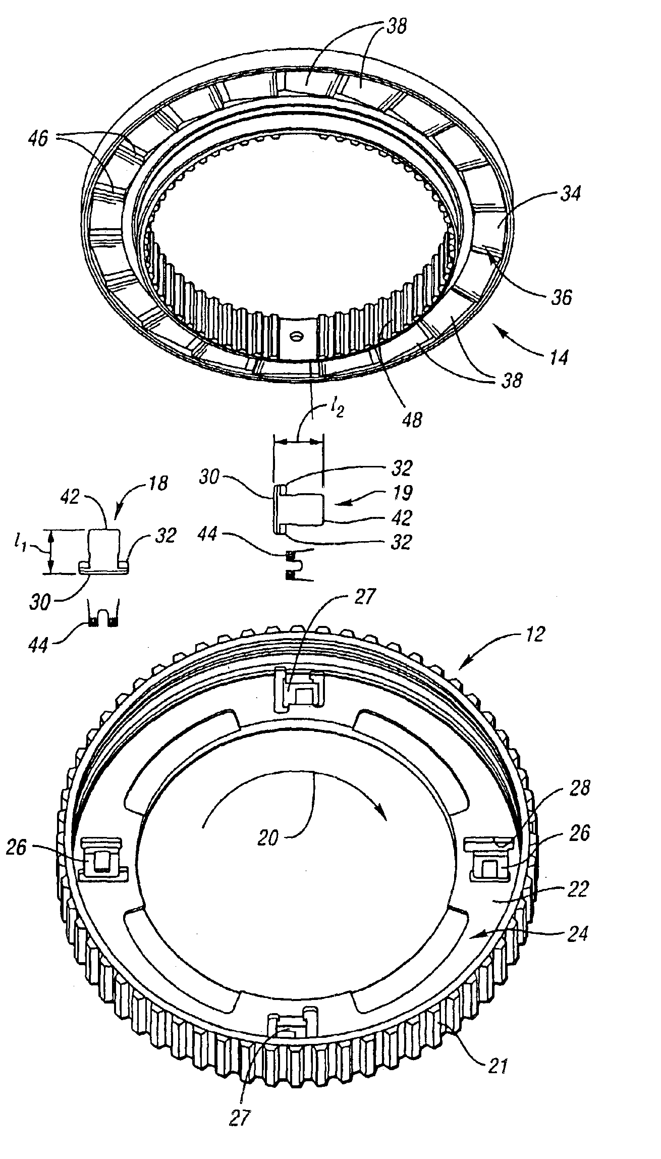
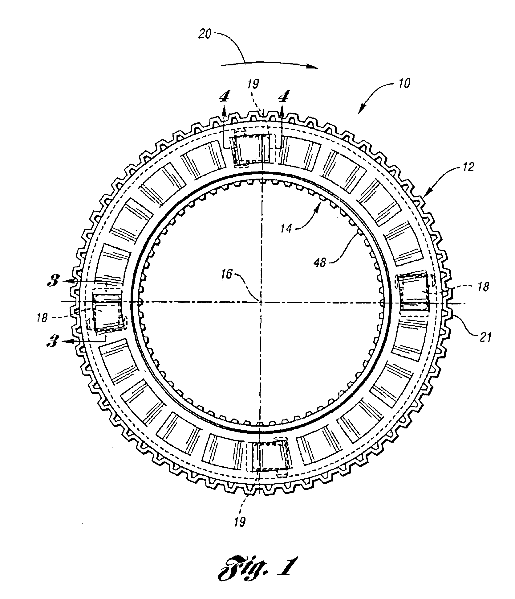
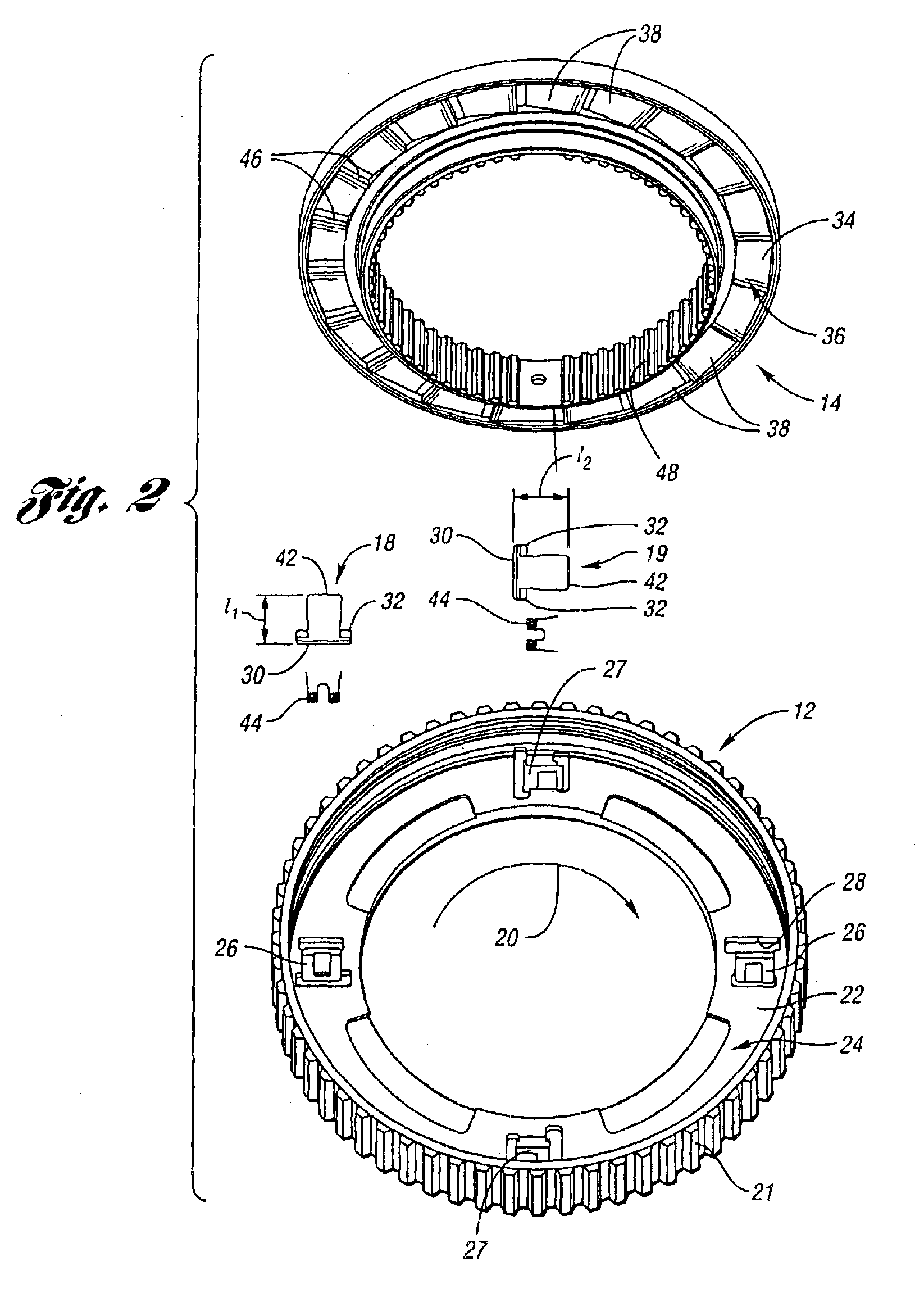
Referring to FIGS. 1 and 2, an exemplary clutch 10 in accordance with the invention includes first and second members, such as a driving member 12 and a driven member 14, both of which are rotatable about a common axis 16. The clutch 10 further includes multiple engaging elements, such as first and second pawls or struts 18 and 19, respectively, disposed between the driving member 12 and the driven member 14, which operate to mechanically couple the driving member 12 to the driven member 14 only when the driving member 12 rotates in a first direction 20 about the axis 16. Alternatively, the function of the members 12 and 14 may be switched such that member 14 imparts a motive force to member 12 when the members 12 and 14 are coupled together. Furthermore, one of the members 12 and 14 may be a stationary member.

In the embodiment shown in FIGS. 1 and 2, the clutch 10 includes two first struts 18 and two second struts 19, and the struts 18 and 19 are spaced approximately ninety degree...


PUM


Abstract

A one-way clutch includes a first member having multiple first recesses, and a second member having multiple second recesses that are alignable with the first recesses. Each recess includes a load-bearing surface. The clutch also includes multiple engaging elements that are engageable with the load-bearing surfaces of the recesses to effect one-way torque transfer between the first and second members. At least one of the engaging elements comprises a non-metallic, compressible material and is configured to compress upon engagement with a respective load-bearing surface of each member to inhibit relative movement of the members.

Description

BACKGROUND OF THE INVENTION1. Field of the InventionThe invention relates to one-way clutches for use in mechanisms such as power transmissions.2. Background ArtClutches are used in a wide variety of applications to selectively couple power from a first rotatable driving member, such as a driving disk or plate, to a second, independently rotatable driven member, such as a driven disk or plate. In one known variety of clutches, commonly referred to as “one-way” or “overrunning” clutches, the clutch engages to mechanically couple the driving member to the driven member only when the driving member rotates in a first direction relative to the driven member. Once so engaged, the clutch will release or decouple the driven member from the driving member only when the driving member rotates in a second, opposite direction relative to the driven member. Further, the clutch otherwise permits the driving member to freely rotate in the second direction relative to the driven member. Such “free...

Claims


Application Information

Patent Timeline
Patent Type & Authority Patents(United States)
IPC IPC(8): F16D41/12F16D41/00
CPCF16D41/125
Inventor RUTH, STEPHEN M.
Owner MEANS IND INC
Why Eureka
Try Eureka