Bone compression devices and systems and methods of contouring and using same

a bone compression device and compression device technology, applied in the field of surgical devices, can solve the problems of increasing affecting the success rate of fusing together four or more levels, and affecting so as to increase the success and reduce the failure rate of bone compression devices

Inactive Publication Date: 2006-10-03
BAYLOR COLLEGE OF MEDICINE
View PDF40 Cites 122 Cited by
  • Summary
  • Abstract
  • Description
  • Claims
  • Application Information

AI Technical Summary

Benefits of technology

[0013]In accordance with the invention, the foregoing advantages have also been achieved through the present bone compression system for placing in communication with at least one bone having a bone radius of curvature, the bone compression system comprising: a plate having a first end, a second end, a first attachment member, a second attachment member, a pre-formed shape, a deformed shape, and at least one elastic shape between the pre-formed shape and the deformed shape, the pre-formed shape having a pre-formed radius of curvature less than the bone radius of curvature, the deformed shape having a deformed radius of curvature greater than the bone radius of curvature, and at least one of the at least one elastic shapes having an elastic radius of curvature that substantially corresponds to the bone radius of curvature; a string having a first end and a second end, wherein the first end of the string is releasably secured to the first attachment member and the second end of the string is releasably secured to the second attachment member; and a tensioner having a shaft and a spool, the tensioner facilitating the movement of the plate from the pre-formed shape to the at least one elastic shape that substantially corresponds to the bone radius of curvature.
[0015]In accordance with the invention, the foregoing advantages have also been achieved through the present method of contouring a bone compression device for placing in communication with at least one bone having a bone radius of curvature, the method comprising the steps of: providing a bone compression device having a plate, the plate including a first end, a second end, a first attachment member, a second attachment member, a pre-formed shape, a deformed shape, and at least one elastic shape between the pre-formed shape and the deformed shape, the pre-formed shape having a pre-formed radius of curvature less than the bone radius of curvature, the deformed shape having a deformed radius of curvature greater than the bone radius of curvature, and at least one of the at least one elastic shapes having an elastic radius of curvature that substantially corresponds to the bone radius of curvature; releasably securing a string having a first end and a second end to the first attachment member and the second attachment member of the plate; applying a tensioner having a shaft and a spool to the string; and actuating the tensioner whereby the string is wrapped around the spool and the plate is moved from the pre-formed shape to at least one of the at least one elastic shapes.
[0019]The bone compression devices and bone compression systems for placing in communication with at least one bone having a bone radius of curvature, methods of maintaining at least two vertebrae in a spatial relationship with each other, and methods of contouring bone compression devices have the advantages of: decreasing the rate of failure of the bone compression devices due to hysteresis; utilize hysteresis to increasing the rate of success of the bone compression devices; decreasing the rate of failure of the bone compression devices when employed on long bones or multiple bones, e.g., three or more vertebrae; and providing compressive forces to the bone to which the bone compression devices are implanted, thereby increasing the grip of the bone compression device on the bone. As mentioned above, it is believed that the present invention will achieve these objectives and overcome the disadvantages of other surgical devices and surgical systems and methods in the field of the invention, but its results or effects are still dependent upon the skill and training of the operators and surgeons.

Problems solved by technology

However, the success rate of fusing together four or more levels is extremely low, i.e., approximately 50% as compared to approximately 95% for two level fusion and 98%–99% for single level fusion.
At least one reason contemplated for the increase in the percentage of failures of the bone compression devices is that the bone compression devices do not substantially correspond to the anatomical curvature of the bone to which they are applied.
As a result of this manipulation, the bone compression device may become permanently deformed, and thus weakened, or experience hysteresis.
One example of hysteresis is illustrated in materials having what has been referred to as “metal memory.” Because of hysteresis, many prior bone compression devices do not remain properly shaped and ultimately fail.
Both the weakening of the bone compression device and hysteresis is further complicated by the use of fasteners, e.g., bone screws or bolts, to secure the bone compression devise to the bone.
These devices, after implantation, experience hysteresis resulting in the bone compression device attempting to revert back to its pre-formed shape, i.e., straight.
As a result, the bone compression device experiences a higher incidence of failure over long lengths.
Such hysteresis is increased by the installation of the fasteners into misshapen fastener holes to secure the bone compression device to the bone.
However, the pre-formed curvature of the bone compression device rarely, if ever, accurately corresponds to the curvature of the bone to which it is to be implanted.
While the amount of manipulation by the surgeon may be lessened, these bone compression devices also experience hysteresis resulting in potential failure of the bone compression device.

Method used


Image

  • Bone compression devices and systems and methods of contouring and using same
  • Bone compression devices and systems and methods of contouring and using same
  • Bone compression devices and systems and methods of contouring and using same

Examples


Embodiment Construction

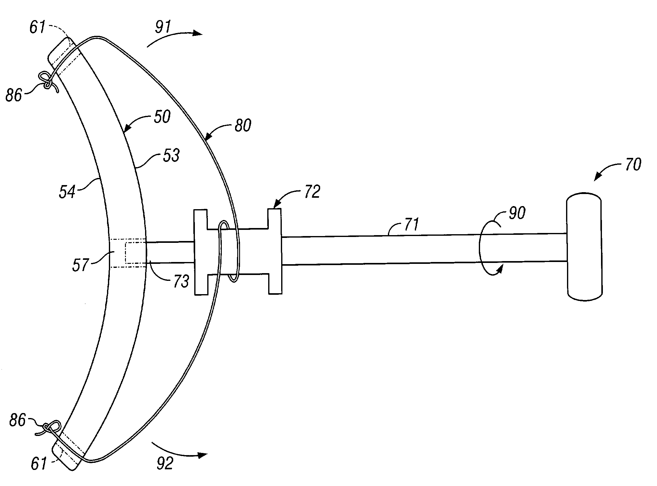
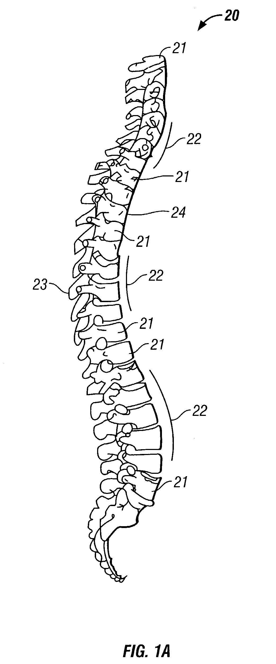
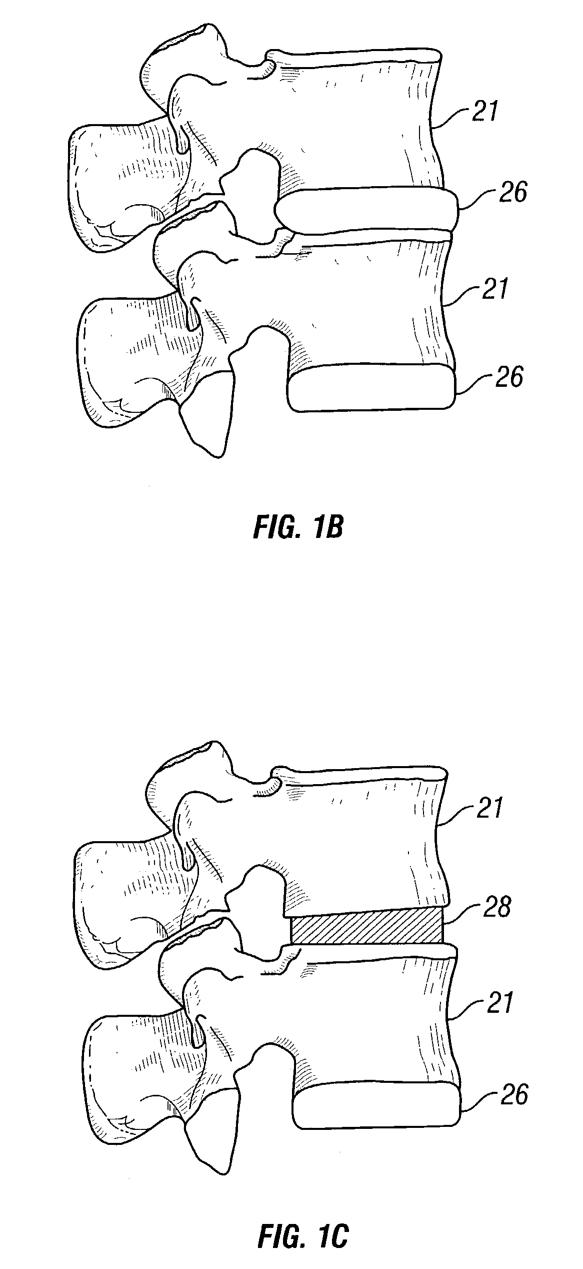
[0034]The present invention is directed to bone compression devices and bone compression systems for maintaining at least one bone in a desired spatial relationship. While the description of the bone compression devices, bone compression systems, and methods of contouring the bone compression devices will be directed to use in connection with two or more vertebrae, it is to be understood that the bone compression devices, bone compression systems, methods of maintaining at least two vertebrae in a spatial relationship with each other, and methods of contouring the bone compression devices of the invention may be used, or performed, in connection with any bone in which it is desired to maintain, or place, at least one bone in a desired spatial relationship, e.g., the pelvis, the femur, the fibula, the tibia, humerus, ulna, radius, or any other bone. For example, the bone compression devices of the invention may be employed in long bone, e.g., femur, and pelvic fracture fixation. Furt...


PUM


Abstract

The invention relates to bone compression devices and bone compression systems, and in particular, to bone compression devices and systems for use in connection with vertebrae. The bone compression devices and bone compression systems are disposed, or installed, along at least one bone to maintain the at least one bone in a desired spatial relationship. Broadly, the invention is directed to a bone compression device for placing in communication with at least one bone having a bone radius of curvature, the bone compression device comprising a plate having a pre-formed shape, a deformed shape, and at least one elastic shape therebetween, the pre-formed shape having a pre-formed radius of curvature less than the bone radius of curvature, the deformed shape having a deformed radius of curvature greater than the bone radius of curvature, and at least one of the at least one elastic shapes having an elastic radius of curvature that substantially corresponds to the bone radius of curvature. The invention is also directed to a bone compression system wherein the plate includes a string attached to each end of the plate and a tensioner for facilitating the movement of the plate from the pre-formed shape to the at least one elastic shape. Methods of maintaining a bone in a spatial relationship and methods of contouring the bone compression devices are also disclosed.

Description

RELATED APPLICATION[0001]This application claims the benefit of U.S. Provisional Patent Application Ser. No. 60 / 344,980, filed Oct. 19, 2001.BACKGROUND OF THE INVENTION[0002]1. Field of the Invention[0003]This invention relates to surgical devices, and in particular, to bone compression devices for maintaining bones, namely, one or more vertebrae, in a desired spatial relationship. The invention also relates to methods for maintaining at least one bone in a spatial relationship and methods for contouring the bone compression devices for use in maintaining bones in a desired spatial relationship.[0004]2. Description of Related Art[0005]The use of bone compression devices in connection with vertebrae are known in the art. Many of these prior bone compression devices are directed to fusing together two or more vertebrae. However, the success rate of fusing together four or more levels is extremely low, i.e., approximately 50% as compared to approximately 95% for two level fusion and 98...

Claims


Application Information

Patent Timeline
Patent Type & Authority Patents(United States)
IPC IPC(8): A61B17/56A61B17/58A61B17/70A61B17/80A61B17/88A61F2/44A61F2/46
CPCA61B17/8004A61B17/808A61B17/8869A61B17/7059
Inventor HEGGENESS, MICHAEL H.
Owner BAYLOR COLLEGE OF MEDICINE
Why Eureka
Try Eureka