End-mill tool with multiple cutting edges

a technology of end-milling tools and workpieces, which is applied in the direction of wood boring tools, shaping cutters, manufacturing tools, etc., can solve the problems of inconvenient for a particular application, weakening the tool, and affecting the quality of the end-milling tool

Inactive Publication Date: 2001-01-02
WARDELL LON J
View PDF16 Cites 61 Cited by
  • Summary
  • Abstract
  • Description
  • Claims
  • Application Information

AI Technical Summary

Problems solved by technology

While such variations have proven successful in various applications, they are also associated with disadvantages and limitations.
For example, such variations may weaken the core diameter of the end-mill cutter, thereby weakening the tool.
Additionally, such noted variations are not suitable for a particular applications (e.g., regarding milling time, rough cut, finish cut, etc.).
Furthermore, known end-mills are not efficient for both rough cutting and finish cutting.
The corners formed along the outside-diameter of the tool point tend to dull with use.
Dull corners at the point of the tool are generally anathema to tools.
However, each additional flute creates additional chips while eliminating chip room, causing chip backing.

Method used


Image

  • End-mill tool with multiple cutting edges
  • End-mill tool with multiple cutting edges
  • End-mill tool with multiple cutting edges

Examples


Embodiment Construction

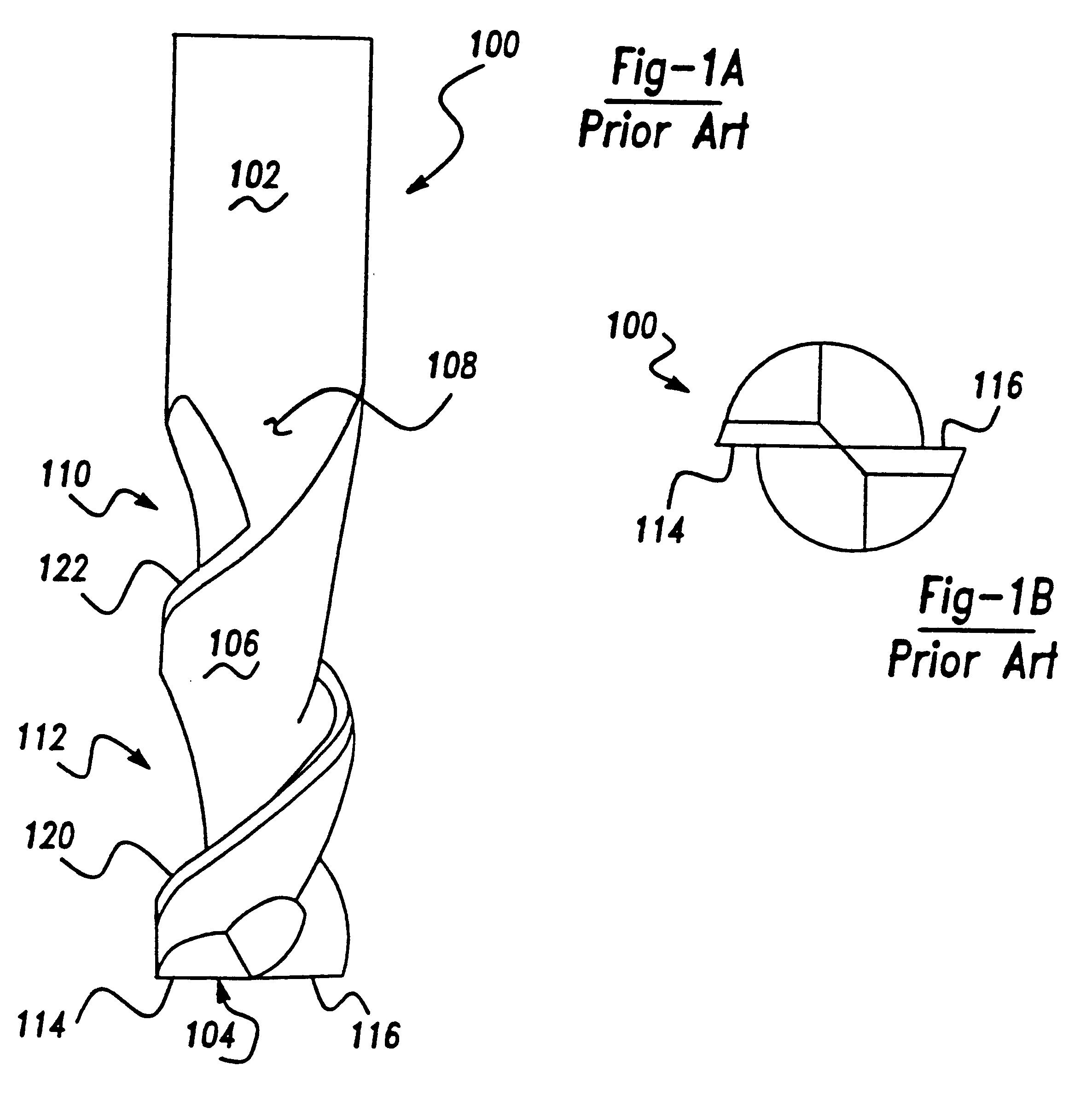
The present invention will now be described more fully hereinafter with reference to the accompanying drawings in which preferred embodiments are shown. It will be appreciated, however, that the present invention may be embodied in many other forms and should not be construed as limited to the embodiments set forth herein. For purposes of clarity, the same reference numerals are used throughout the drawings to consistently identify identical or equivalent element. In the discussion that follows, it will be understood that no priority of function is meant to be attributed to the terms "first" and "second". In this regard, these terms are used for identification purposes only.

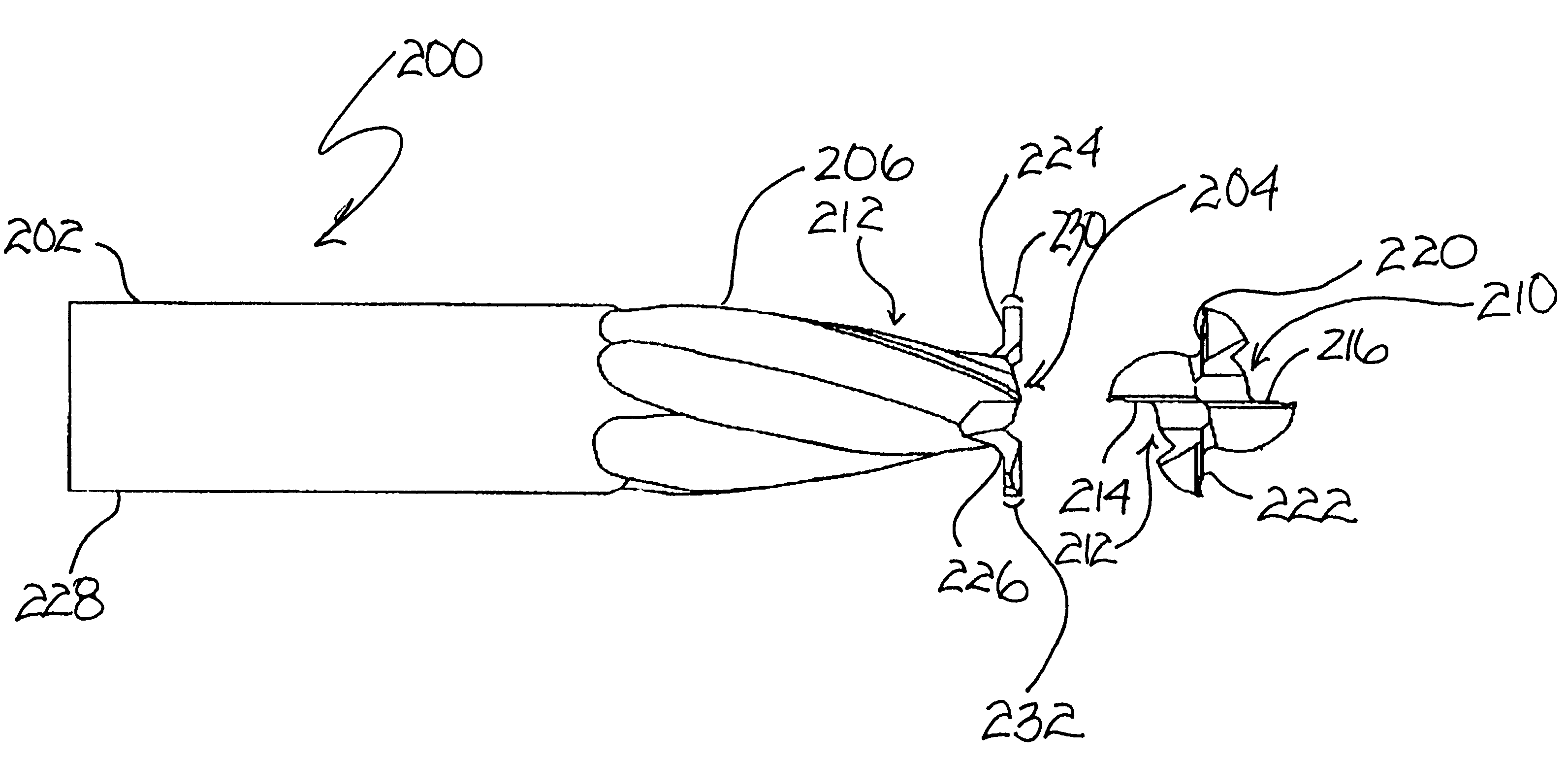
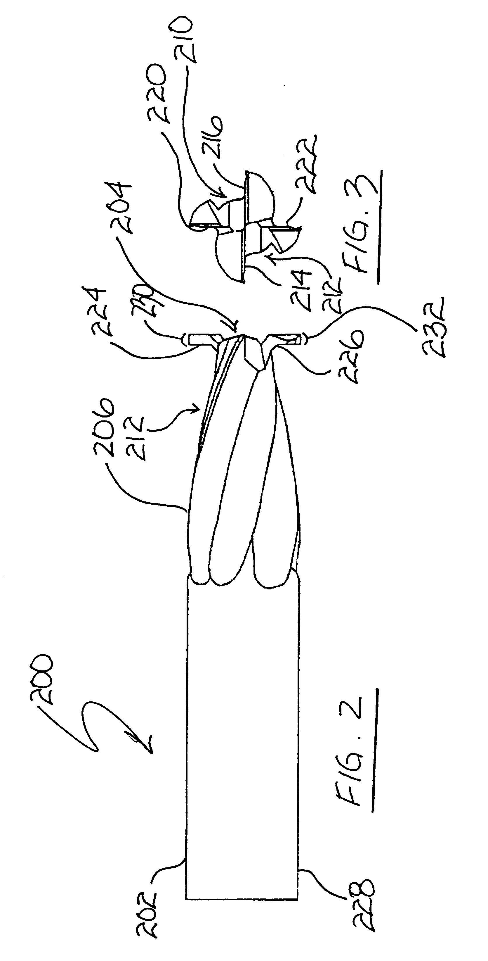
Referring generally to FIGS. 2 through 3 of the drawings, an end-mill tool constructed in accordance with the first preferred embodiment is identified with reference numeral 200. FIG. 2 illustrates a side view of the end-mill 200 of the present invention. FIG. 3 illustrates an end view of the end-mill of FIG. 2.

T...


PUM

PropertyMeasurementUnit
angleaaaaaaaaaa
angleaaaaaaaaaa
helix angleaaaaaaaaaa

Abstract

The present invention provides an end-mill tool which includes a shank, a point, and a main body portion located intermediate the shank and the point. A first flute is formed on the main body portion along a first helix. A second flute is formed on the main body portion along a second helix. The first and second flutes preferably extend helically along the body of the tool. Two distinct helical cutting surfaces are defined by the first flute and the second flute. The point of the tool includes two additional cutting edges formed by ears extending outward from the point of the tool adjacent the first flute and the second flute.

Description

1. Technical Field of the InventionIn general, the present invention relates to machining of a workpiece. More particularly, the present invention relates to end-mill tools for milling a workpiece and a related method.2. Background of the InventionRotary cutting end-mill tools are used for various machining operations on workpieces. Such machine operations are generically referred to as milling operations and include the forming of slots, keyways, pockets, and the like. Several considerations related to end-mill tool design include time for completing a machining operation, amount of material removed in a cut, quality of the cut, and wear on the tool itself during the milling operation.End-mill tools are formed from materials such as tungsten carbide, high speed steel, ceramic, and other advanced materials and coatings and typically include a "shank" portion, a "body" portion and a "point". The shank portion is located towards one end of the end-mill tool and is generally cylindrica...

Claims


Application Information

Patent Timeline
Patent Type & Authority Patents(United States)
IPC IPC(8): B23C5/10
CPCB23C5/10B23B2220/12B23C2210/084B23C2210/088Y10T408/9097B23C2210/486Y10T407/1948Y10T407/1954Y10T407/1966B23C2210/203
Inventor WARDELL, LON J.
Owner WARDELL LON J
Why Eureka
Try Eureka