Friction stir weld tools

a technology of friction stir and weld tools, which is applied in the direction of manufacturing tools, soldering devices, auxillary welding devices, etc., can solve the problems of pin tool strength, durability, wear resistance and stress management, and many improvements initiated, and achieves the effect of increasing tool life and great traverse speed

Inactive Publication Date: 2007-10-02
NASA
View PDF41 Cites 61 Cited by
  • Summary
  • Abstract
  • Description
  • Claims
  • Application Information

AI Technical Summary

Benefits of technology

[0014]As can be seen from the prior art, there exists a need for a FSW tool which prov

Problems solved by technology

While many improvements have been initiated, none are believed to satisfactoril

Method used


Image

  • Friction stir weld tools
  • Friction stir weld tools
  • Friction stir weld tools

Examples


Embodiment Construction

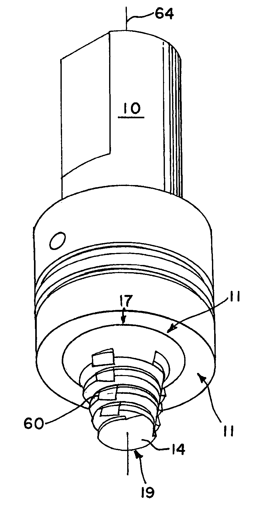
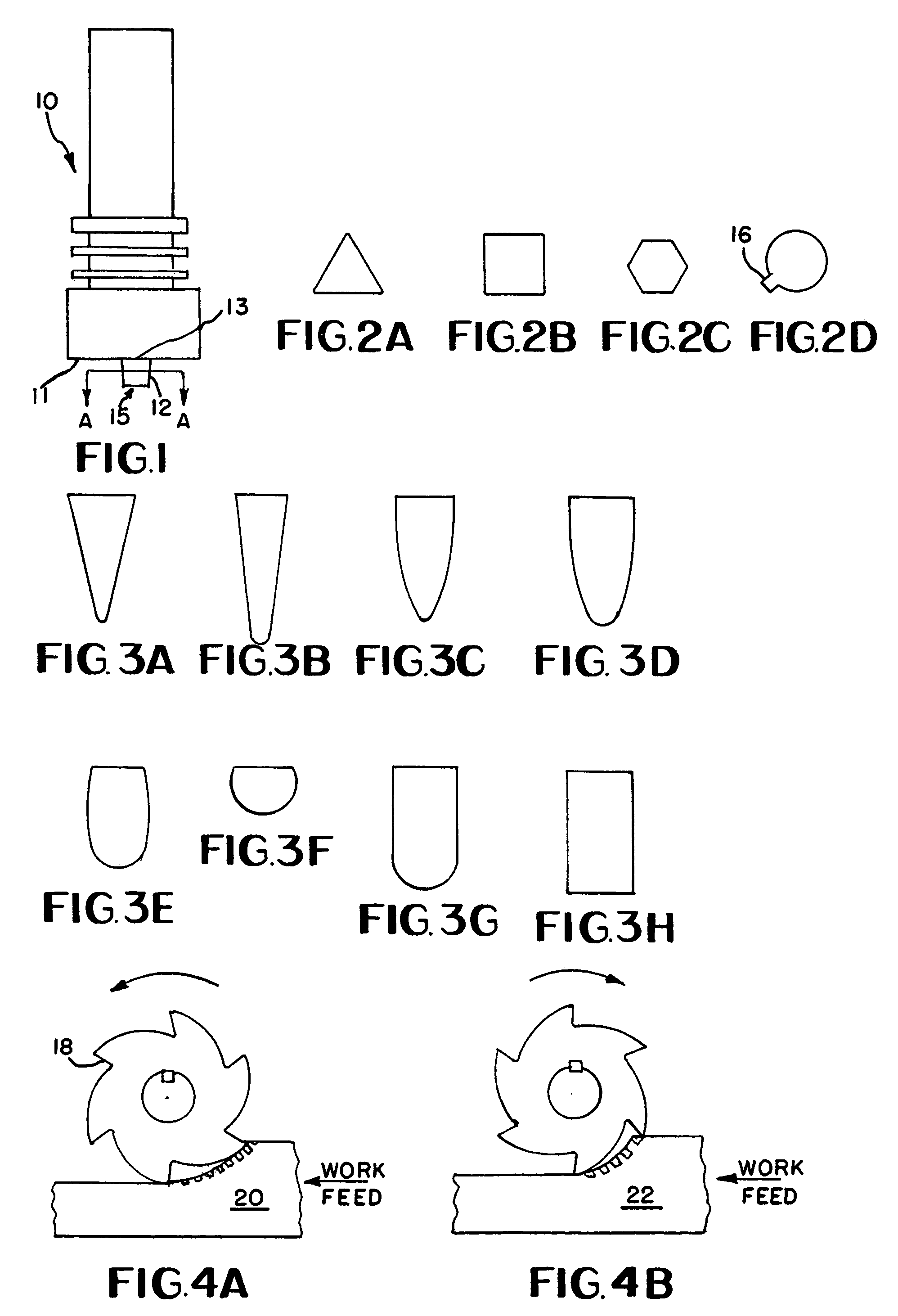
[0028]FIG. 1 shows a tool body with integral shoulder 10 and integral smaller diameter protruding support pin 12 in accordance with the presently preferred embodiment of the present invention. While tool bodies with integral shoulders have been known in the art, the support pin 12 is believed to be new. The body, shoulder and pin 10, 11 and 12 rotate together about rotational axis 64. The pin 12 is selected from material for toughness, fracture, wear resistance, and other characteristics. The pin 12 may have a coating and / or sleeve intermediate the pin 12 and any of the alternatively preferred embodiments of tool sleeves as shown in FIGS. 3A-3H. The currently preferred embodiment of a tool sleeve is illustrated in FIGS. 7 and 8 as sleeve 14 connected to pin 12.

[0029]FIG. 2 shows cross section embodiments taken along the line A-A of FIG. 1. These or other cross sectional embodiments could also be utilized. Any of the planar segments shown may be useful to prevent rotation of sleeve 1...


PUM

PropertyMeasurementUnit
Flow rateaaaaaaaaaa
Toughnessaaaaaaaaaa
Circumferenceaaaaaaaaaa

Abstract

A friction stir weld tool sleeve is supported by an underlying support pin. The pin material is preferably selected for toughness and fracture characteristics. The pin sleeve preferably has a geometry which employs the use of an interrupted thread, a plurality of flutes and/or eccentric path to provide greater flow through. Paddles have been found to assist in imparting friction and directing plastic metal during the welding process.

Description

STATEMENT OF GOVERNMENT INTEREST[0001]The invention described herein was made in part by an employee of the United States Government and may be manufactured and used by or for the Government of the United States of America for governmental purposes without the payment of any royalties thereon or therefor.BACKGROUND OF THE INVENTION[0002]1. Field of the Invention[0003]This invention relates to friction stir welding pin-tools, and more particularly to pin design and the pin surface geometry which engages a workpiece.[0004]2. Description of Related Art[0005]Friction Stir Welding (FSW) is a solid-state welding process that uses a non-consumable rotating pin-tool to make linear welds. Typical pin-tools consist of a cylindrical “shoulder” and a smaller diameter protruding “pin”. The process is initiated by plunging the rotating pin-tool into a weld joint until the shoulder is in intimate contact with the surface of the work piece. After the pin-tool has reached its final plunge depth a dw...

Claims


Application Information

Patent Timeline
IPC IPC(8): B23K20/12B23K37/00
CPCB23K20/1255
Inventor CARTER, ROBERT W.PAYTON, LEWIS N.
Owner NASA
Why Eureka
Try Eureka