Optical scanner, image forming apparatus, and image forming method

a technology of image forming apparatus and optical scanner, which is applied in the direction of recording apparatus, mechanical recording, instruments, etc., can solve the problem that the main scanning direction of the electrostatic latent image to be formed on the photoreceptor drum b>31/b> cannot be determined

Inactive Publication Date: 2012-09-25
KYOCERA DOCUMENT SOLUTIONS INC
View PDF10 Cites 2 Cited by
  • Summary
  • Abstract
  • Description
  • Claims
  • Application Information

AI Technical Summary

Benefits of technology

[0021]According to the present invention, a timing when the incidence of a laser beam having an emission intensity equal to or higher than the reference emission intensity is detected by the laser beam detector, in short, a start timing of the electrostatic latent image formation controlled by the timing controller for exposure start, can be kept constant, and thus, a position of the electrostatic latent image in the main scanning direction on the photoreceptor can be kept constant.
[0022]Particularly, in an image forming apparatus dealing with colors and comprising a plurality of optical scanners according to the present invention, the position of image formation of an electrostatic latent image by each of the optical scanners are constant in the main scanning direction on the photoreceptor, even when the emission intensity of the laser beam source is changed for every optical scanner. This prevents the occurrence of the color deviation in a color image produced by overlapping images formed on respective photoreceptors.
[0025]Additionally, the present invention may be understood as an invention of an image forming apparatus comprising one or a plurality of the optical scanners. An image forming apparatus comprising the optical scanner can hold a position in the main scanning direction of an image to be formed on a paper sheet constant, while at the same time, preventing the occurrence of color deviation in a color image.

Problems solved by technology

This causes a problem that the position in the main scanning direction of a electrostatic latent image to be formed on the photoreceptor drum 31 cannot be determined.

Method used


Image

  • Optical scanner, image forming apparatus, and image forming method
  • Optical scanner, image forming apparatus, and image forming method
  • Optical scanner, image forming apparatus, and image forming method

Examples


Embodiment Construction

[0033]In what follows, the embodiment of the present invention is described with reference to the accompanying drawings to provide more understanding of the present invention. Additionally, the following embodiment is merely an example of the present invention, having no intention to limit the technical scope of the present invention.

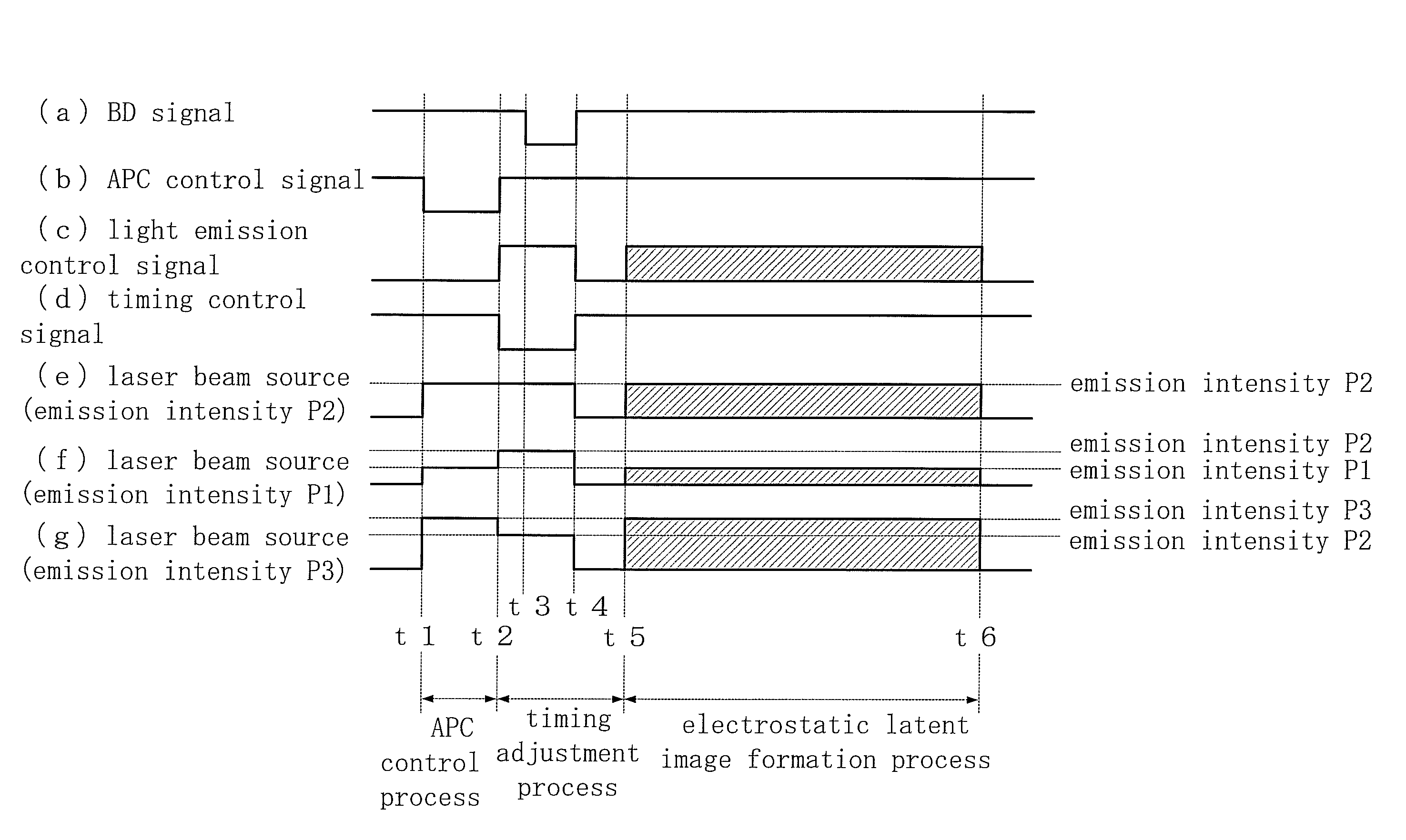
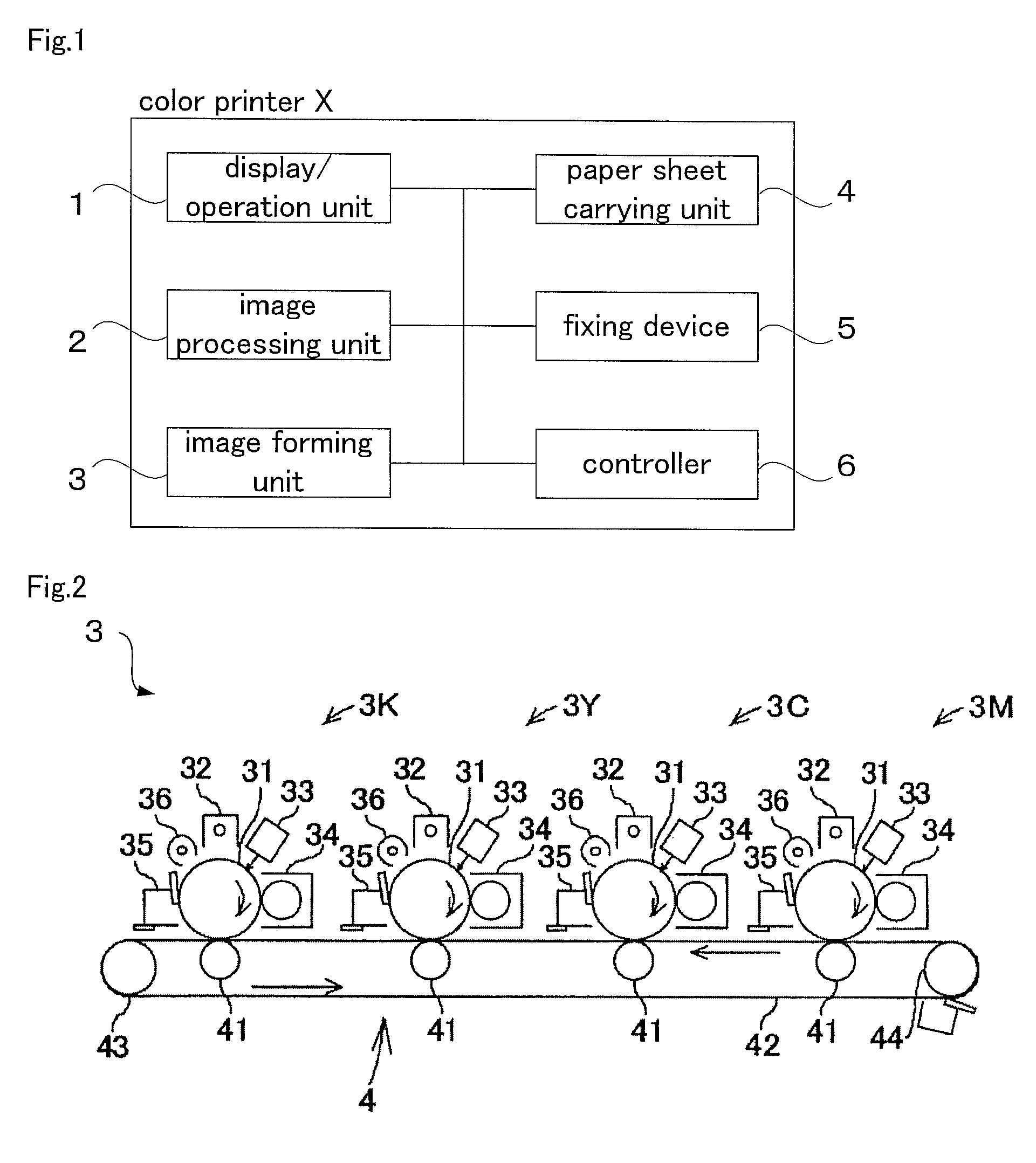
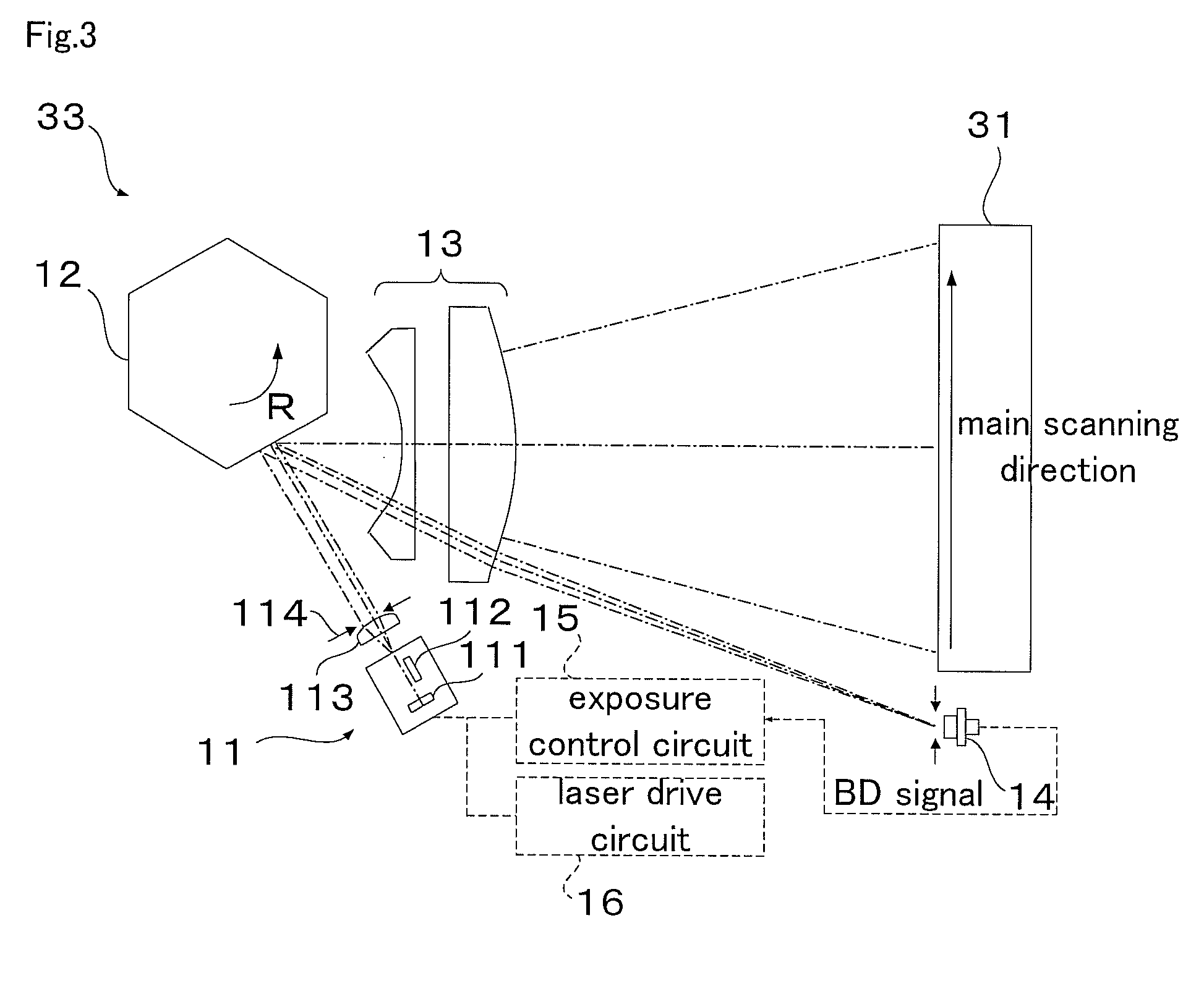
[0034]Here, FIG. 1 is a block diagram showing a general configuration of a color printer X according to one embodiment of the present invention; FIG. 2 is a schematic configuration diagram of an image forming unit 3 in the color printer X; FIG. 3 is a pattern diagram showing a general configuration of an optical scanner 33 provided in the image forming unit 3; FIG. 4 is a timing chart for explaining exposure processing in every line by the optical scanner 33; FIG. 5 is a circuit diagram of a laser sensor 14, and FIG. 6 shows one example of operation characteristics of the laser sensor 14.

[0035]In addition, the color printer X according to the present em...


PUM


Abstract

The emission intensity of a laser beam source, at a time when a laser beam emitted from the laser beam source and scanned by an optical scanning device becomes incident to a laser beam detector provided in a predetermined position on the scanning path of the laser beam in order to hold a position of an electrostatic latent image formed on a photoreceptor constant in the main scanning direction, while at the same time, changing the emission intensity of the laser beam, is set so as to become the consistently same emission intensity regardless of a change in emission intensity at the time of electrostatic latent image formation onto a photoreceptor. This allows the detection timing of a laser beam by a laser beam detector to be kept constant.

Description

CROSS-REFERENCE TO PRIOR APPLICATION[0001]The present application claims priority from Japanese Patent Application No. 2008-017709, filed on Jan. 29, 2008, and is hereby incorporated by reference in its entirety herein.BACKGROUND OF THE INVENTION[0002]1. Field of the Invention[0003]The present invention relates to an optical scanner for forming an electrostatic latent image on a photoreceptor by scanning a laser beam, that is emitted on the basis of image data, onto the photoreceptor, and an image forming apparatus comprising thereof, and more particularly, to a technology for holding a position for image formation of the electrostatic latent image constant in the main scanning direction on the photoreceptor.[0004]2. Description of the Related Art[0005]Conventionally, there have been image forming apparatuses, such as copiers, printers, facsimiles, and MFPs comprising thereof, which form a color image by overlapping toner images of four colors: magenta (M), cyan (C), yellow (Y), and...

Claims


Application Information

Patent Timeline
Patent Type & Authority Patents(United States)
IPC IPC(8): B41J2/435B41J2/48G01D15/14
CPCG03G15/043G03G15/326G06K15/1219G06K15/1214G03G15/0435
Inventor OKADA, MASANORI
Owner KYOCERA DOCUMENT SOLUTIONS INC
Why Eureka
Try Eureka