Magnification systems

a technology of magnification system and magnification function, which is applied in the field of magnification system, can solve the problems of inconvenient object whose geometries consume a great deal of space, lens cannot fully perform the magnification function, and the problem of attaching a magnification system to a flat rigid object,

Inactive Publication Date: 2012-10-23
SAMO ZUHAIR K
View PDF11 Cites 11 Cited by
  • Summary
  • Abstract
  • Description
  • Claims
  • Application Information

AI Technical Summary

Problems solved by technology

Attaching a magnification system to a flat rigid object, such as an LCD monitor, is a problem when used with objects possessing different geometries.
Likewise, if a person desires a magnifier supported by a base, that may be inconvenient for objects whose geometries consume a great deal of space, such as LCD monitors.
There may also be a problem when the geometries of an apparatus supporting a lens do not allow for proper orienting of the lens about the two axes defining a plane normal to a user's line of sight.
If not properly oriented relative to a user's line of sight, a lens cannot fully perform its magnification function.
Such problems may be even greater when such a user suffers from visual impairments and may depend upon the proper functioning of the magnifier for his or her ability to read.

Method used


Image

  • Magnification systems
  • Magnification systems
  • Magnification systems

Examples


Embodiment Construction

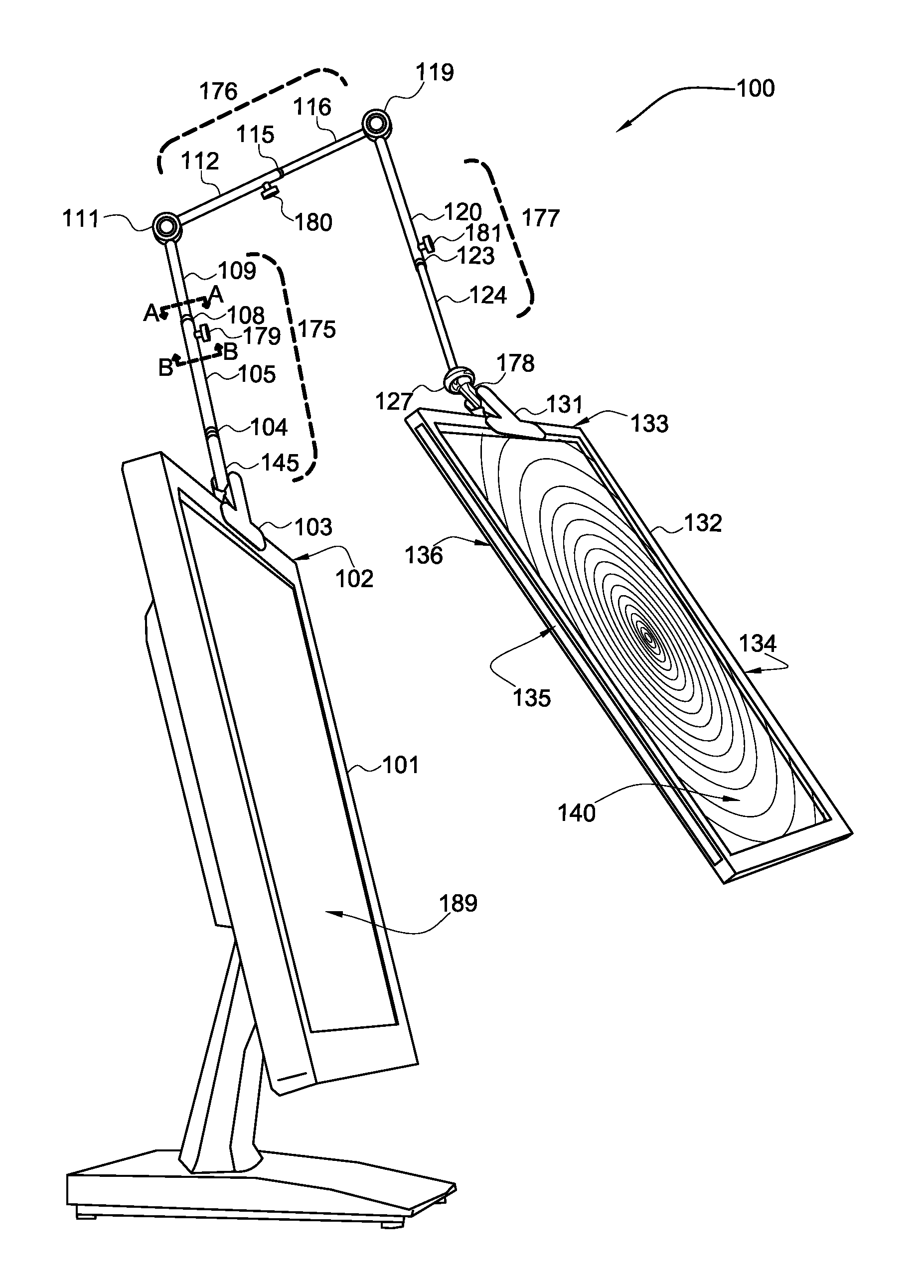
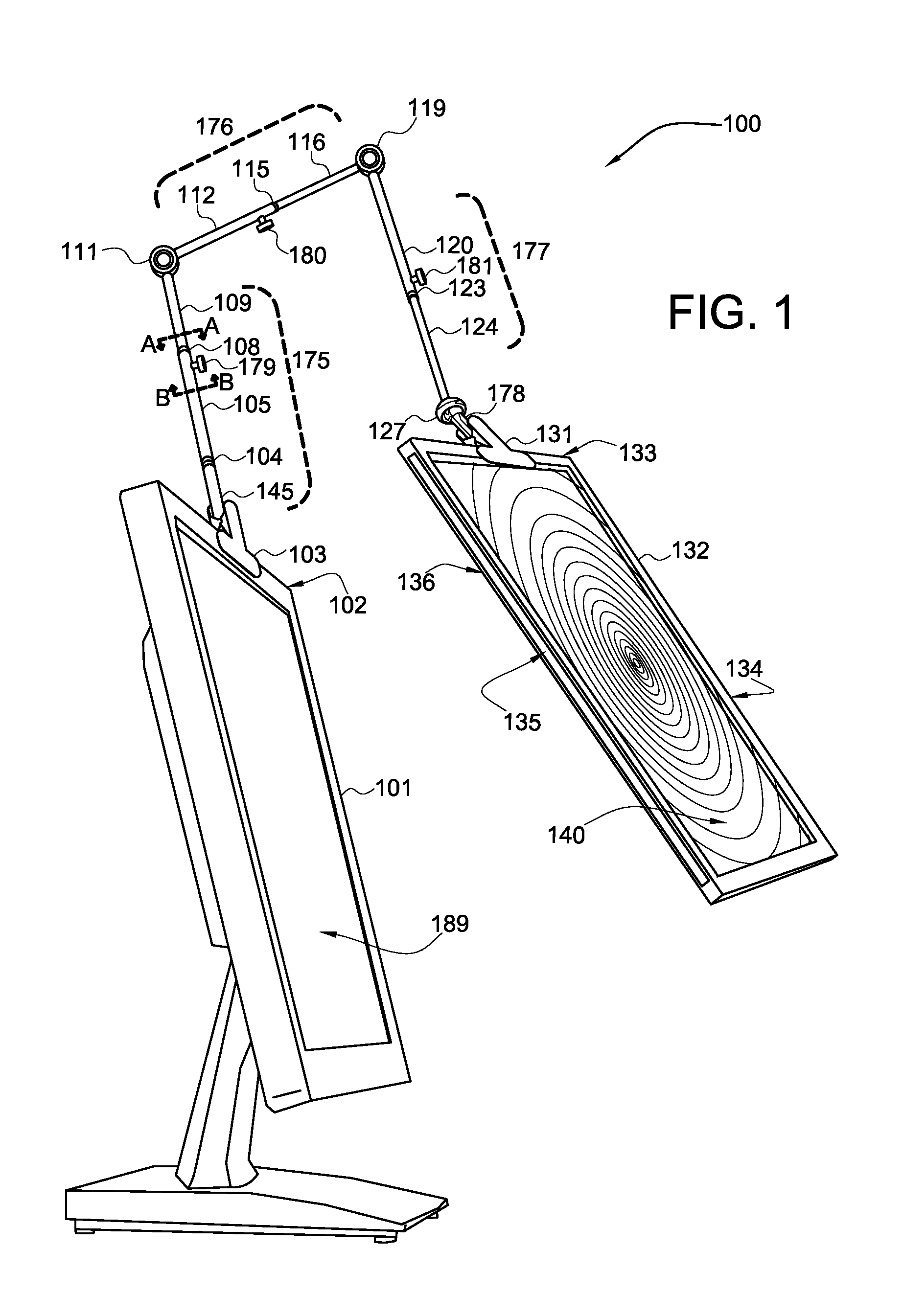
[0033]FIG. 1 shows a perspective view of a magnifier 100 of the magnifying systems 200, illustrating the magnifier supported by a clamp 103 attached to an LCD monitor 101, according to a preferred embodiment of the present invention.

[0034]Magnifier 100 preferably comprises at least one first telescoping arm 175, preferably at least one second telescoping arm 176, preferably at least one third telescoping arm 177, preferably at least one first articulating joint 111, preferably at least one second articulating joint 119, preferably at least one omni-directional positioner such as ball joint 127, preferably at least one lens compartment 132 and preferably at least one lens 140, as shown.

[0035]First telescoping arm 175, second telescoping arm 176 and third telescoping arm 177 preferably comprise lightweight plastics materials and are preferably cylindrical or tubular in shape. Each telescoping arm preferably comprises a total length of 10 inches when fully retracted, and preferably a t...


PUM


Abstract

A system to support at least one magnification device on a readable digital display screen upon a base that is interchangeable with a clamp, and that is further capable of omni-directionally orienting the supported magnification device about at least two axes.

Description

CROSS REFERENCE TO RELATED APPLICATION[0001]The present application is related to and claims priority from prior provisional application Ser. No. 61 / 224,989, filed Jul. 13, 2009, entitled “FLEXIBLE LCD MAGNIFICATION SYSTEM WITH CONVERSION BASE ATTACHMENT FOR TABLE TOP LIGHTED LAMP MAGNIFIER,” the contents of which is incorporated herein by this reference and are not admitted to be prior art with respect to the present invention by the mention in this cross-reference section.BACKGROUND[0002]This invention relates to providing a system of interchangeably supportable and omni-directionally positional magnification devices. More particularly, this invention relates to providing a system to support a magnification device on a readable digital display screen upon a base that is interchangeable with a clamp, and that is further capable of omni-directionally orienting the supported magnification device about at least two axes.[0003]There is sometimes a need to magnify screen images supporte...

Claims


Application Information

Patent Timeline
Patent Type & Authority Patents(United States)
IPC IPC(8): G02B27/02
CPCG02B25/005G02B27/021
Inventor SAMO, ZUHAIR K.
Owner SAMO ZUHAIR K
Why Eureka
Try Eureka