Supercharge Your Innovation With Domain-Expert AI Agents!

Lens barrel assembly

a technology of lens barrel and assembly, which is applied in the direction of mountings, instruments, cameras, etc., can solve the problems of blocking foreign substances, affecting the effect of lens barrel assembly,

Active Publication Date: 2012-11-13
SAMSUNG ELECTRONICS CO LTD
View PDF4 Cites 9 Cited by
  • Summary
  • Abstract
  • Description
  • Claims
  • Application Information

AI Technical Summary

Benefits of technology

[0012]The lens barrel assembly may further include an elastic supporting unit, which is arranged between the rotating unit and the lens barrel and provides elasticity to the rotating unit in a direction against a direction in which the rotating unit rotates.

Problems solved by technology

When a protective cover is attached to a front side of a lens barrel assembly toward an object, the influx of foreign substances may be blocked.
Furthermore, a series of operations for attaching a lens barrel assembly, including holding a lens barrel assembly, removing a protective cover, and attaching the lens barrel assembly to a photographing device are complex and require several seconds.
Furthermore, even if a protective cover is attached to the rear side of the lens barrel assembly, foreign substances may enter into the lens barrel assembly when the lens barrel assembly is attached to a photographing device in environments with strong winds or a large amount of dust.

Method used


Image

  • Lens barrel assembly
  • Lens barrel assembly
  • Lens barrel assembly

Examples


Embodiment Construction

[0029]The attached drawings for illustrating embodiments are referred to in order to gain a sufficient understanding of the embodiments, the merits thereof, and the objectives accomplished by the implementation of the embodiments.

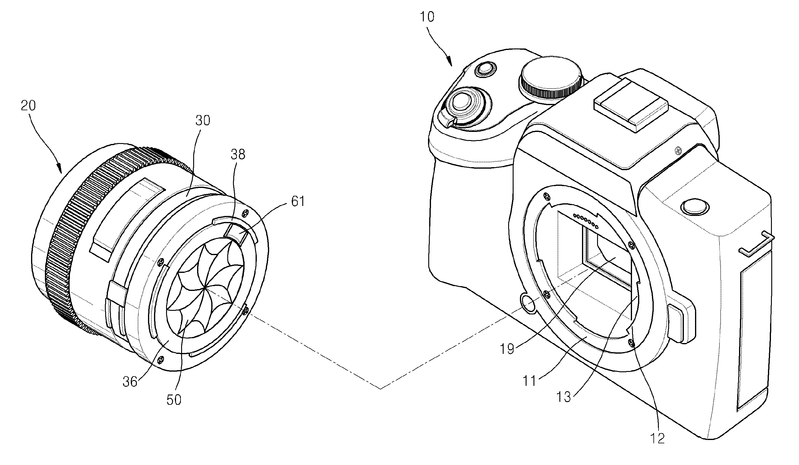
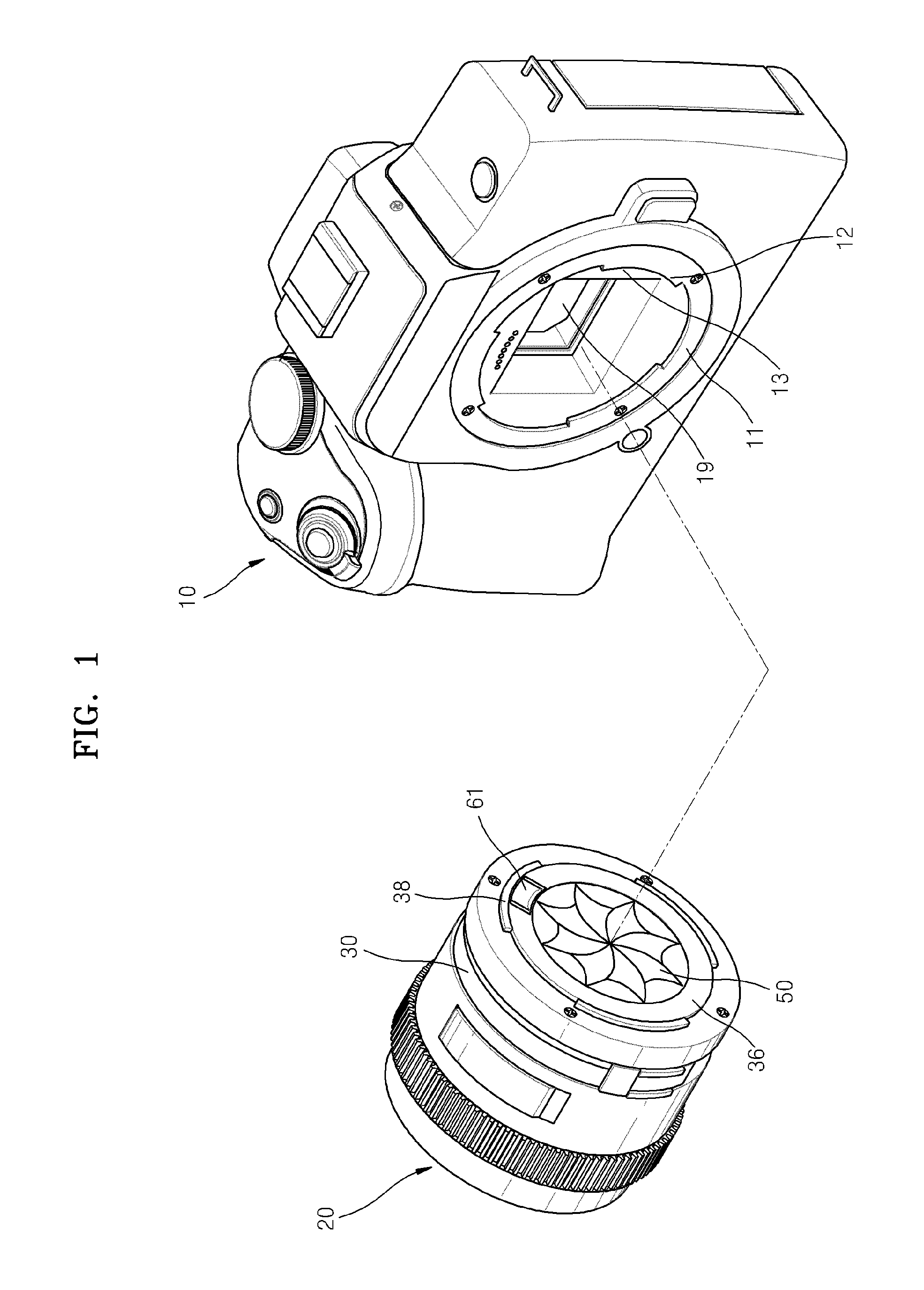
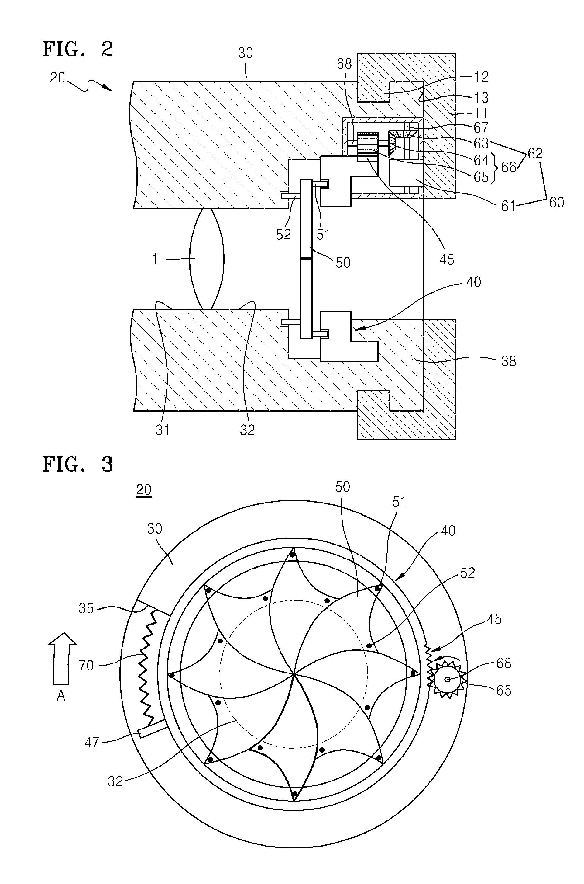
[0030]FIG. 1 is a perspective view of operation of a lens barrel assembly 20, according to an embodiment, and FIG. 2 is a lateral sectional view of a portion of the lens barrel assembly 20 of FIG. 1.

[0031]The lens barrel assembly 20 shown in FIGS. 1 and 2 may be detachably attached to an attachment mount 11 of a camera 10.

[0032]The lens barrel assembly 20 may include a lens barrel 30 having an inlet 31, which surrounds a lens 1 and through which external light enters, and an outlet 32, through which light that has passed through the lens 1 exits, a rotating unit 40 attached to the lens barrel 30, a shield plate 50, which may be connected to the lens barrel 30 and the rotating unit 40 and may move, and a driving unit 60, which rotates the rotating unit 40.

[0...


PUM


Abstract

A lens barrel assembly that is attached to and detached from a camera includes: a lens barrel, which surrounds a lens and includes an inlet through which an external light enters; and an outlet through which light, which has passed through the lens, exits; a rotating unit, which is attached to the lens barrel such that the rotating unit rotates in a circumferential direction of the lens barrel; a shield plate, which has a first side rotatably connected to the rotating unit and a second side rotatably connected to the lens barrel and moves between a position of closing the outlet and a position of opening the outlet as the rotating unit rotates; and a driving unit, which contacts the camera when the lens barrel is attached to the camera, generates rotation force from friction force, and rotates the rotating unit.

Description

CROSS-REFERENCE TO RELATED PATENT APPLICATION[0001]This application claims the priority benefit of Korean Patent Application No. 10-2010-0078487, filed on Aug. 13, 2010, in the Korean Intellectual Property Office, the disclosure of which is incorporated herein in its entirety by reference.BACKGROUND[0002]1. Field of the Invention[0003]Embodiments relate to a lens barrel assembly, and more particularly, to a lens barrel assembly including a shield plate, which operates automatically in linkage with attaching or detaching of the lens barrel assembly to a photographing device for protecting a lens.[0004]2. Description of the Related Art[0005]From among photographing devices, such as digital cameras, models to which lens barrel assemblies are detachably attached are widely used. Users of such photographing devices use lens barrel assemblies having various functions according to photographing purposes, and selectively attach lens barrel assemblies required for photographing to the photog...

Claims


Application Information

Patent Timeline
Patent Type & Authority Patents(United States)
IPC IPC(8): G03B17/00G02B7/02
CPCG03B11/043G03B11/048G03B17/14G03B11/04G03B17/04
Inventor YOUN, YEO-TAK
Owner SAMSUNG ELECTRONICS CO LTD
Features
  • R&D
  • Intellectual Property
  • Life Sciences
  • Materials
  • Tech Scout
  • Unparalleled Data Quality
  • Higher Quality Content
  • 60% Fewer Hallucinations
Learn More