Rear-slidable extension in a fiber optic equipment tray

a fiber optic equipment and rear-sliding technology, applied in the field of fiber optic equipment, can solve the problems of requiring extensive labor, requiring significant time and labor to walk back and forth from the rear section to the front section of the equipment rack during an installation, and limiting the amount of pivoting

Inactive Publication Date: 2012-12-04
CORNING OPTICAL COMM LLC
View PDF8 Cites 91 Cited by
  • Summary
  • Abstract
  • Description
  • Claims
  • Application Information

AI Technical Summary

Benefits of technology

[0012]The extension may comprise a shelf and a cable management tray. The shelf moves over the base when the extension extends from and retracts toward the fiber optic equipment tray. At least one plunger and slot may be used to releasably retain the cable management tray in planar alignment with the fiber optic equipment tray when the extension is retracted. When the extension is extended, the cable management tray may be allowed to pivot downwardly. A pivot stop limits the amount the cable management tray may pivot, which may be at least about 20° or more. The pivot stop may include at least one pivot bracket having a stop groove and a pivot pin. As the cable management tray pivots, the pivot bracket may rotate around the pivot pin until the stop groove contacts a stop pin, thereby limiting the amount of pivot of the cable management tray.

Problems solved by technology

Even with advancements in access to fiber optic modules, the labor associated with installing fiber optic modules and making optical connections is significant.
Because data distribution centers are typically large facilities with significant numbers of equipment racks, walking back and forth from the rear section to the front section of the equipment rack during an installation can take significant time.
In either scenario, fiber optic cables are installed in the rear section of the equipment rack and the fiber optic modules and connections are installed from the front of the equipment rack thereby requiring extensive labor.

Method used


Image

  • Rear-slidable extension in a fiber optic equipment tray
  • Rear-slidable extension in a fiber optic equipment tray
  • Rear-slidable extension in a fiber optic equipment tray

Examples


Embodiment Construction

[0065]Reference will now be made in detail to the preferred embodiments, examples of which are illustrated in the accompanying drawings, in which some, but not all embodiments of the invention are shown. Indeed, the invention may be embodied in many different forms and should not be construed as limited to the embodiments set forth herein; rather, these embodiments are provided so that this disclosure will satisfy applicable legal requirements. Whenever possible, like reference numbers will be used to refer to like components or parts.

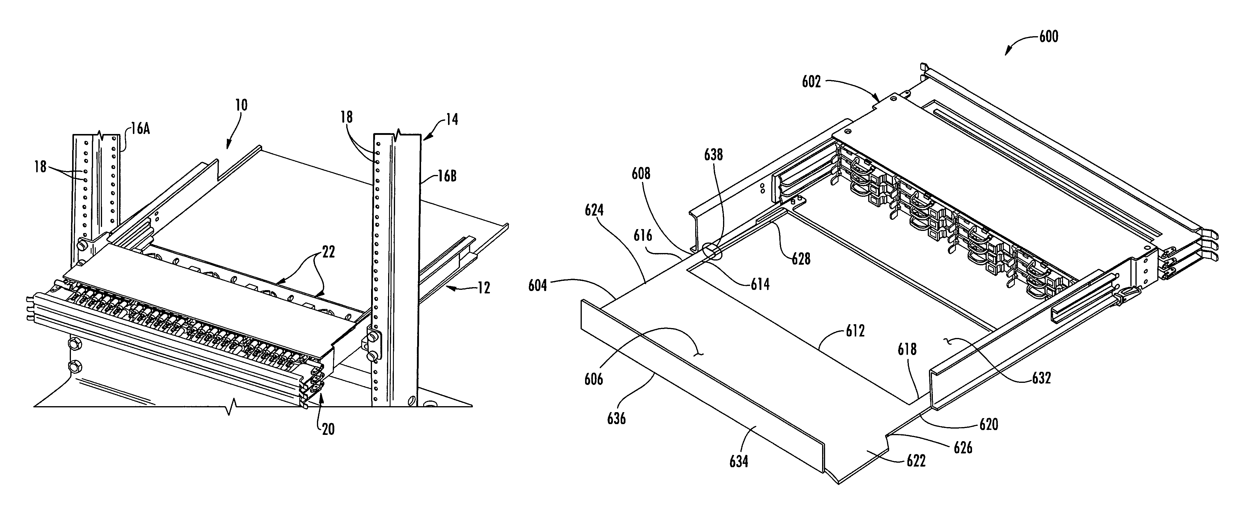
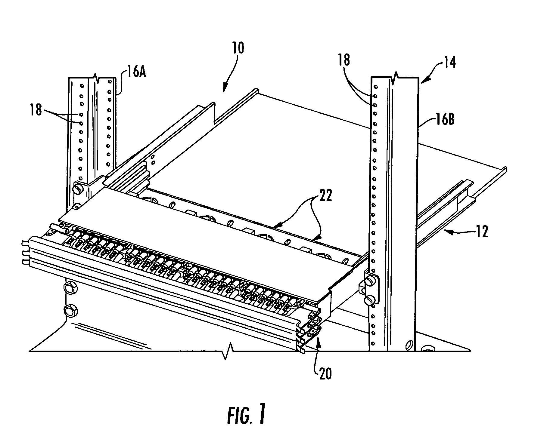
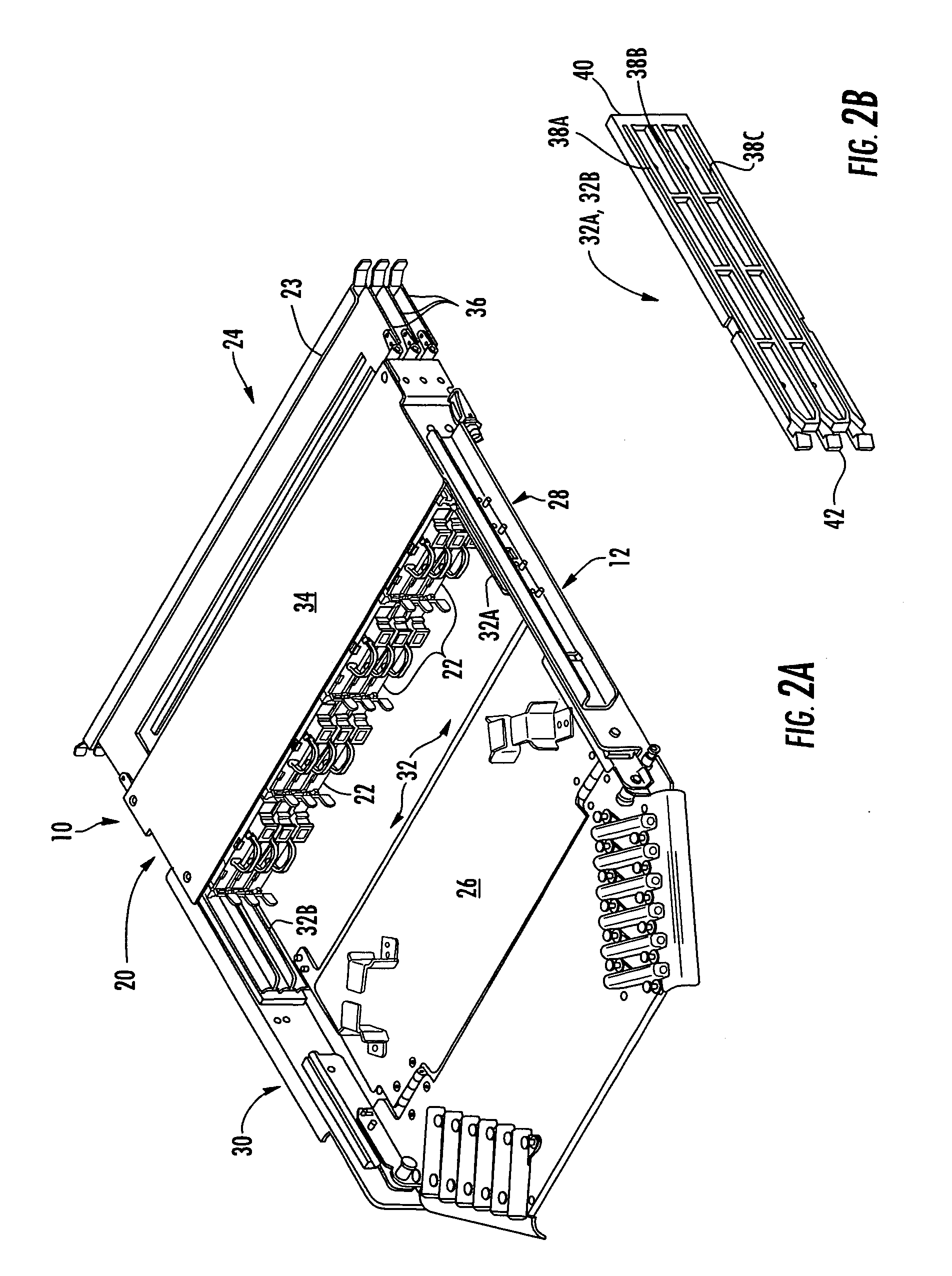
[0066]Embodiments disclosed in the detailed description include fiber optic equipment that supports one or more rear-installable fiber optic modules. The fiber optic modules are configured to support fiber optic connections. The fiber optic equipment is comprised of a chassis defining a front end and a rear section. At least one guide system is disposed in the chassis and configured to receive at least one fiber optic module. The guide system may be pr...


PUM


Abstract

A fiber optic apparatus having a fiber optic equipment tray and an extension adapted to receive, organize and manage fiber optic cables routed to the fiber optic equipment tray is disclosed. The fiber optic equipment tray has a front, a rear, a base, and at least one extension rail. The extension movably attaches to the fiber optic equipment tray at the extension rail and, thereby, slidably extends from and retracts toward the rear of the fiber optic equipment tray. The extension comprises a shelf and a cable management tray hingedly attached to the shelf. The shelf moves over the base when the extension extends from and retracts toward the fiber optic equipment tray. The cable management tray is in planer alignment with the fiber optic equipment tray when the extension is retracted, and allowed to pivot downwardly when the extension is extended. At least one furcation plug tray attaches to the cable management tray. The at least one furcation plug tray adapted to mount at least one furcation plug to which fiber optic cables may be connected.

Description

RELATED APPLICATIONS[0001]The present application claims priority to U.S. Provisional Patent Application Ser. No. 61 / 190,538 filed Aug. 29, 2008 entitled “High Density Data Center Hardware, Assemblies and Components,” which is incorporated herein by reference in its entirety.[0002]The present application also claims priority to U.S. Provisional Patent Application Ser. No. 61 / 197,068 filed Oct. 23, 2008 entitled “High Density Data Center Hardware, Assemblies and Components,” which is incorporated herein by reference in its entirety.[0003]The present application is related to co-pending U.S. patent application Ser. No. 12 / 323,415 entitled “Independently Translatable Modules and Fiber Optic Equipment Trays In Fiber Optic Equipment” which is incorporated herein by reference in its entirety.[0004]The present application is related to co-pending U.S. patent application Ser. No. 12 / 323,423 entitled “Rear-Installable Fiber Optic Modules and Equipment” which is incorporated herein by referen...

Claims


Application Information

Patent Timeline
Patent Type & Authority Patents(United States)
IPC IPC(8): G02B6/00G02B6/46
CPCG02B6/4452G02B6/4455
Inventor COOKE, TERRY L.KLAVUHN, TORY A.DEAN, JR., DAVID L.GARCIA, JUANLOPEZ, MANUELGONZALEZ, JUAN MIGUEL
Owner CORNING OPTICAL COMM LLC
Why Eureka
Try Eureka