
Counterbore hole chamfer depth measuring apparatus and method

a technology of depth measurement and chamfer, which is applied in the direction of measuring devices, measuring gauges, instruments, etc., can solve the problem of difficult to achieve accurate placement of calipers

Inactive Publication Date: 2012-12-25
HONG FU JIN PRECISION IND (SHENZHEN) CO LTD +1
View PDF11 Cites 13 Cited by
  • Summary
  • Abstract
  • Description
  • Claims
  • Application Information

AI Technical Summary

Benefits of technology

The present patent is about a measuring apparatus and method for checking the depth of chamfered holes in devices. The apparatus includes a positioning member and a support member, and a measuring device. The positioning member has a guiding block with engaging holes, and the support member has screws that engage with the engaging holes. The measuring device includes a measurement instrument, a spring member, a measuring head portion, and a sleeve. The apparatus and method can accurately measure the depth of chamfered holes, ensuring proper connection of parts.

Problems solved by technology

However, accurate placement of the caliper is not easily achieved, which can effect the precision of measuring the chamfer.

Method used


Image

  • Counterbore hole chamfer depth measuring apparatus and method
  • Counterbore hole chamfer depth measuring apparatus and method
  • Counterbore hole chamfer depth measuring apparatus and method

Examples


Embodiment Construction

[0013]Embodiments of the present measuring apparatus and method will now be described in detail below and with reference to the drawings.

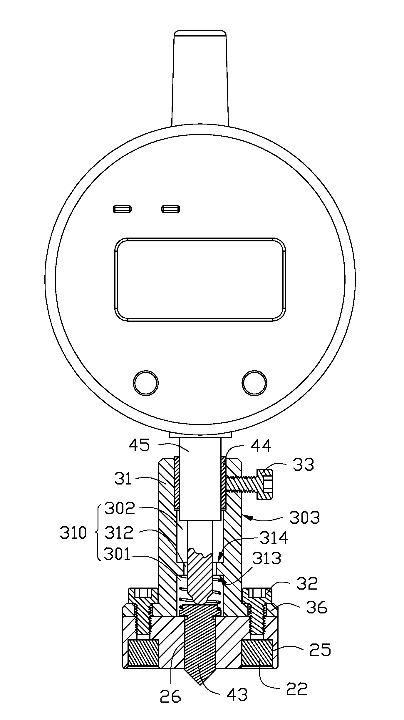
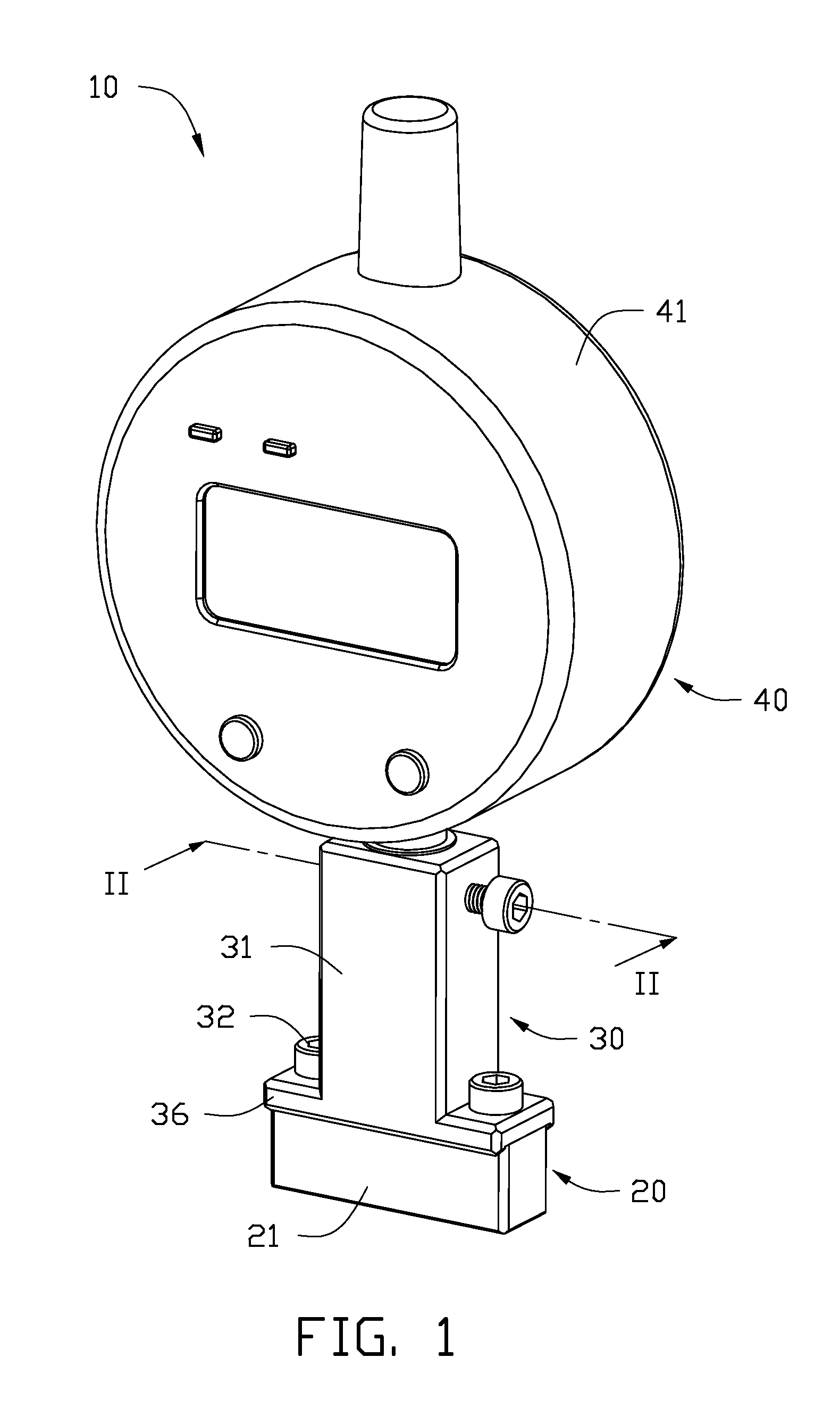
[0014]Referring to FIG. 1, a measuring apparatus 10 for whether a counterbore hole chamfer is done to the proper depth, includes a positioning member 20, a support member 30, and a measuring device 40.

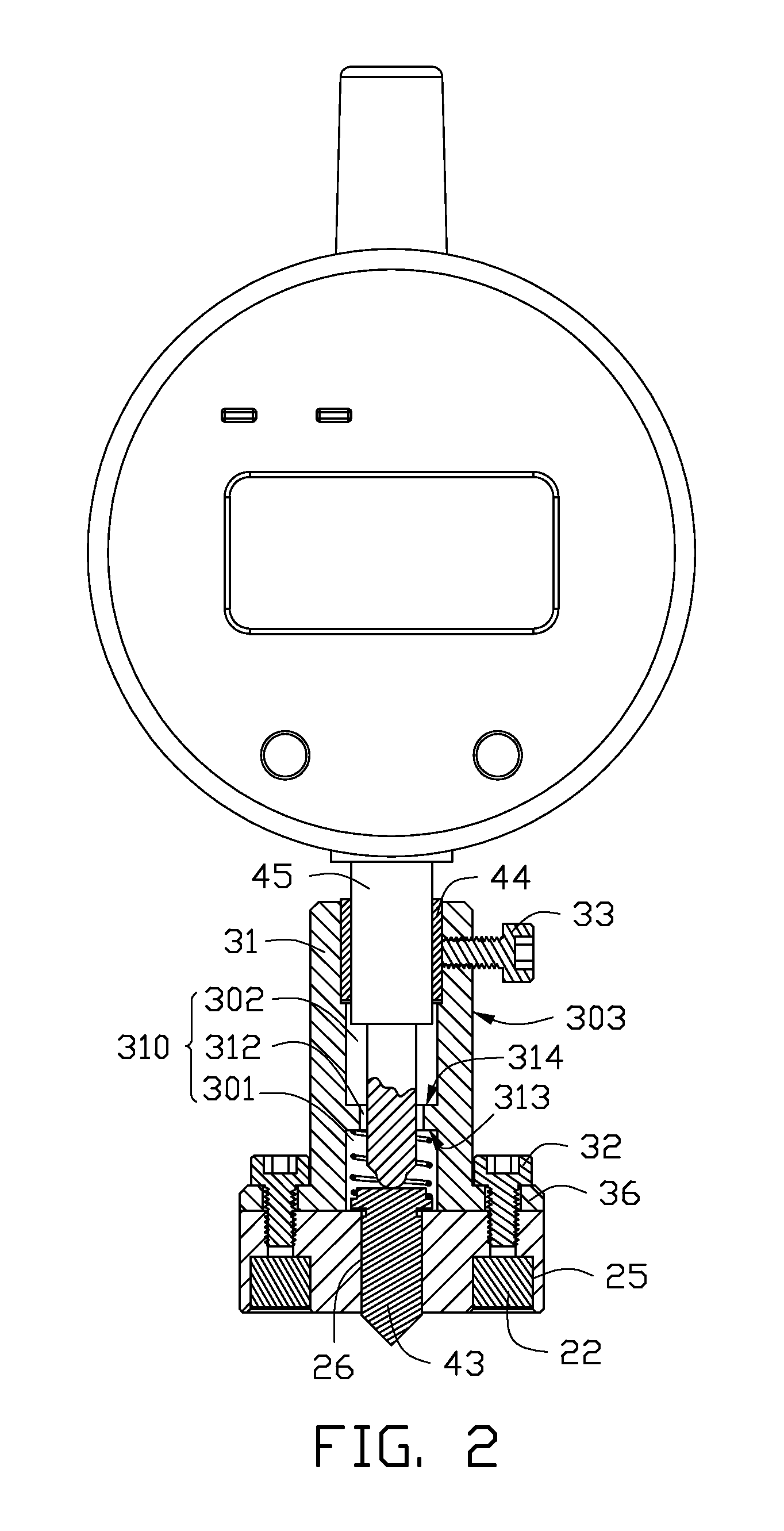
[0015]Referring also to FIGS. 2 and 3, the positioning member 20 includes a guiding block 21 and two magnetic blocks 22. The guiding block 21 is substantially rectangular, and includes a first surface 23 and an opposite second surface 24. The guiding block 21 includes a guiding hole 26 defined through the first surface 23 and the second surface 24, two recesses 25 defined in the first surface 23, and two first engaging holes 27 defined in the second surface 24 and in communication with the recesses 25, respectively. A central axis of each of the first engaging holes 27 is aligned with that of the corresponding recess 25. The magnetic blocks 22 are com...


PUM


Abstract

A measuring apparatus for measuring a counterbore hole chamfer depth of a workpiece, includes a positioning member having a guiding hole aligned with the counterbore hole of the workpiece, a support member having a receiving hole aligned with the guiding hole, and a measuring device supported by the support member. The measuring device includes a gauge, a retractable pole connected to the gauge and extending into the receiving hole, and a measuring head portion connected to the retractable pole and movably received in the guiding hole. The measuring head portion has a cone-shaped end for abutting on an inner wall of the counterbore hole chamfer, thereby making the measuring head portion move back in the guiding hole and the retractable pole retract. The gauge is configured for calculating and displaying the depth of the counterbore hole chamfer based on the distance the retractable pole retracts.

Description

BACKGROUND[0001]1. Technical Field[0002]The present disclosure relates to a counterbore hole chamfer depth measuring apparatus and a related method.[0003]2. Description of Related Art[0004]In assembly of various devices, articles with counterbore holes are widely used for being connected to each other with counterbore head screws. The counterbore holes are usually chamfered for facilitating the mounting of the counterbore head screws. A depth of the counterbore hole chamfer needs to be checked, to ensure that heads of the screws are flush with the surrounding surface.[0005]Currently, a caliper is usually used to test the counterbore hole chamfer depth. However, accurate placement of the caliper is not easily achieved, which can effect the precision of measuring the chamfer.[0006]What is needed, therefore, is a counterbore hole chamfer depth measuring apparatus and method, which can overcome the above shortcomings.BRIEF DESCRIPTION OF THE DRAWINGS[0007]Many aspects of the present mea...

Claims


Application Information

Patent Timeline
Patent Type & Authority Patents(United States)
IPC IPC(8): G01B5/18
CPCG01B3/28
Inventor ZHANG, BING-JUN
Owner HONG FU JIN PRECISION IND (SHENZHEN) CO LTD
Learn More