Lockable utility box lid

a utility box lid and lockable technology, applied in the field of utility box lids, can solve the problems of limited design, limited ability of conventional utility box lids to be securely attached to enclosure boxes, limited ability of other methods of securing utility box lids to enclosure boxes, etc., to prevent, restrict and/or deter unauthorized access.

Active Publication Date: 2013-01-08
RIX ZACHARY DANIEL
View PDF39 Cites 15 Cited by
  • Summary
  • Abstract
  • Description
  • Claims
  • Application Information

AI Technical Summary

Benefits of technology

[0013]Another aspect of the present invention includes a bolt comprising a bolt head having an atypical pentagonal cavity thereby further restricting, preventing and / or deterring unauthorized access to the utility box enclosure.
[0014]Yet another aspect of the present invention includes an atypical tool comprised of a tool head configured to correspond with the pentagonal cavity of the bolt head and a reduced tool shank configured to circumnavigate the plurality of tool apertures thereby allowing for the clamping mechanisms to be expanded and contracted as needed for authorized accessibility to the utility box enclosure.

Problems solved by technology

With an extraordinary number of box enclosures still in place today, the foremost limitation of conventional utility box lids is that they lack the ability to be adequately fastened.
Other utility box lids are equipped to be fastened using threaded fasteners but the heads of the fasteners are typically exposed and easily accessible thereby minimally restricting unauthorized access.
Thereafter, other methods of securing a utility box lid to the enclosure box were designed but also suffer from limitations.
However, the commonality is that the head of the fasteners are also upwardly exposed and easily accessible thus allowing for the possibility of unauthorized manipulation of the fastener and access to the contents housed in the enclosures.
In addition to the same susceptibility to granular particles, padlocks expose another set of disadvantages in that they can be easily cut or pried open.
Contemplating the retrofit option, one disadvantage exists in that its attachment to an existing lid requires several holes to be accurately drilled to accept at least eight bolts.
This method of implementation is largely impractical given that conventional lids are generally made of sturdy materials of varying thicknesses such as concrete, steel and the like.
Thus, drilling a number of holes would be time consuming and cost prohibitive thereby restricting its potential applications.
Further contemplating either method of implementation, another significant disadvantage is that device is dependant on a sheer horizontal lower lip to be present within the enclosure box in order for the lid to be retained as intended.
This dependency further limits its potential use to existing enclosures with lips or alternatively, it would increase preparation time where modification to the enclosure box would be necessary.
Yet another disadvantage is noticed with this locking mechanism in that the device requires no more than 180 degrees of rotation to disengage the locking rods.
Further, the mechanism appears not to have an adequate restraint function to keep the rotational portion of locking mechanism from freely spinning Hence, an object other than the intended key could be forced into the key aperture to manipulate the locking mechanism with a half-turn to gain access to the enclosure therefore further diminishing the effectiveness of the mechanism.
This method has several apparent disadvantages in that: 1) the installer of the device is required to undermine beneath the bottom edge of the enclosure to fit the device in position which can be time consuming and problematic; 2) the enclosure lid requires preparation in that a slot must be cut into the lid so as to accept the upper tab of the device which can be time consuming and problematic; 3) obstructions present in the enclosure such as conduit, pipe, cabling, meters, etc. or in cases where the bottom opening of the enclosure is sealed with a cement slurry mixture or other hardened material will further prolong or prevent installation; 4) the keyed padlock or similar locking device mounted above the surface of enclosure lid creates a tripping hazard for pedestrians where applications in paths of travel occur furthering its limitations.

Method used


Image

  • Lockable utility box lid
  • Lockable utility box lid
  • Lockable utility box lid

Examples


first embodiment -

First Embodiment-Operation-FIGS. 8E thru 8F

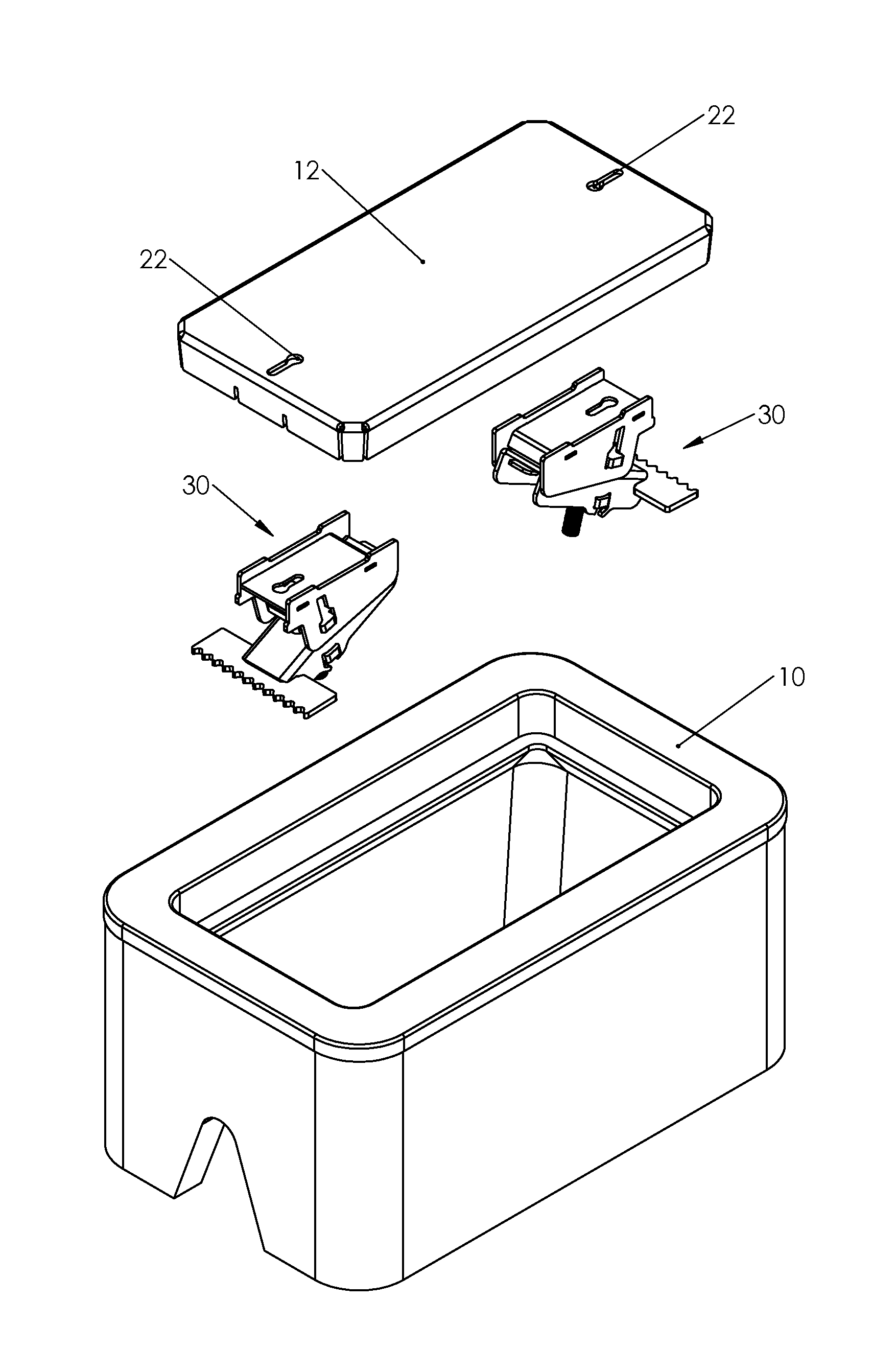
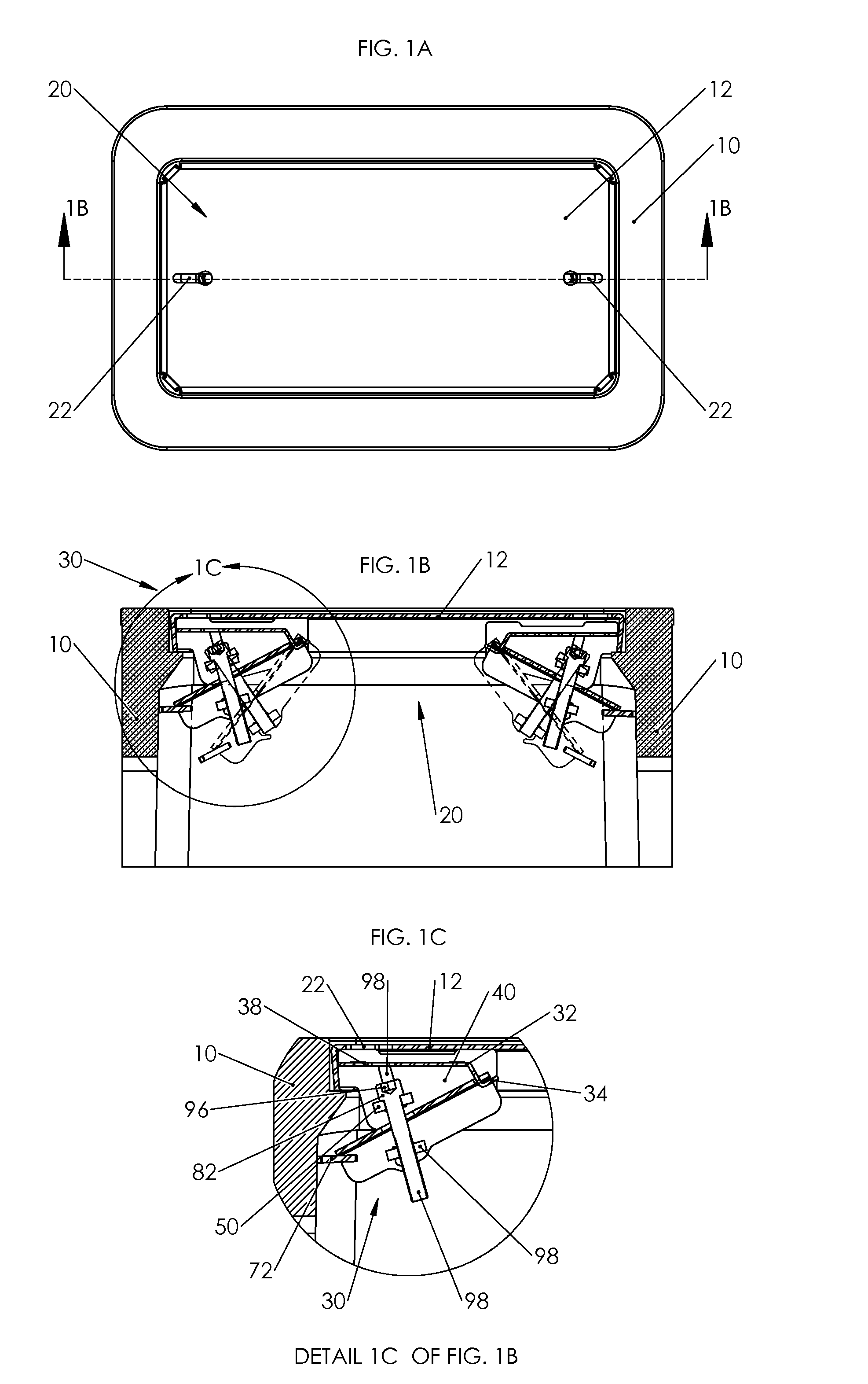
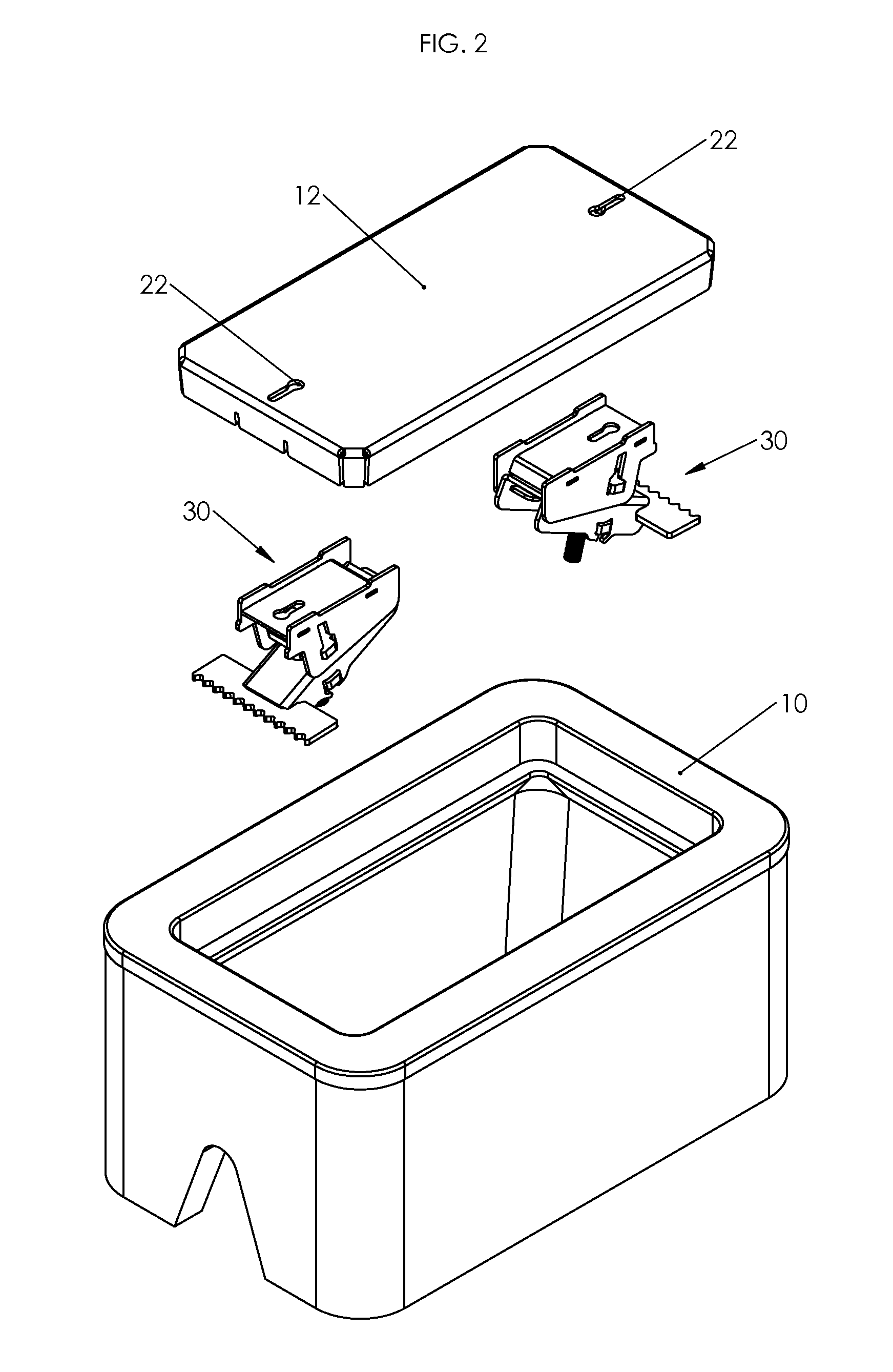
[0070]The sequential illustrations of FIGS. 8A thru 8F depict of a method of inserting the handled tool 92 into the clamping mechanism 30 as follows: The tool head 96 is first inserted downwardly through the first circular end of the upper keyhole-shaped tool aperture 22 of the box lid 12 followed by a second lateral movement of the handled tool 92 towards the second linear end of the upper keyhole-shaped tool aperture 22. With this second movement, the reduced tool shank 98 allows for the movement of the handled tool 92 into the second linear end of the upper keyhole-shaped tool aperture 22 while the tool head 96 passes beneath the same second end of the upper keyhole-shaped tool aperture 22 of the box lid 12. The third movement is again a downward so that the tool head 96 passes through the second circular end of the lower keyhole-shaped tool aperture 38 of the lock plate 32. The fourth movement is again a lateral movement (opposite the s...


PUM


Abstract

One embodiment of a lockable utility box lid (20) for a utility box enclosure (10) comprises a box lid (12) having at least one upper tool aperture (22) and at least one clamping mechanism (30) coupled to the underside of the box lid (10). The clamping mechanism (30) includes at least one lower tool aperture (38) of a lock plate (32) oppositely corresponding to the upper tool aperture (22) of the box lid (12). The lock plate (32) may be coupled to a plurality of side plates (40). The clamping mechanism (30) may also include a pivot arm (60) coupled with a jaw plate (72). A pivot tab (34) of the lock plate (32) may be inserted through a pivot tab aperture (76) of the pivot arm (60) thereby creating a fulcrum point. A back plate (50) inserted into a plurality of back plate apertures (52) of the side plates (40) and a threaded plate (64) inserted into a plurality threaded plate apertures (68) of the pivot arm (60) may be aligned to receive a bolt (80). A bolt head (82) of the bolt (80) may be aligned beneath the lower tool aperture (38). A handled tool (92) may be inserted first through the upper tool aperture (22) and again through the lower tool aperture (38) where it may insert into a bolt head cavity (84) of the bolt head (82) wherein a rotation of the handled tool (92) will produce a transitional movement of the at least one clamping mechanism (30) between an engaged and disengaged position.

Description

CROSS REFERENCE TO RELATED APPLICATIONS[0001]This application claims the benefit of Provisional Patent Application No. 61 / 154,425, filed 2009 Feb. 22 by the present inventor.FEDERALLY SPONSORED RESEARCH[0002]Not ApplicableSEQUENCE LISTING[0003]Not ApplicableBACKGROUND-FIELD[0004]This application generally relates to utility box lids, specifically to a utility box lid with one or more integral clamping mechanism(s).BACKGROUND-PRIOR ART[0005]Conventional utility boxes are used to house various utilities including, but limited not to, electrical, telecommunication, fiber optic, water and other similar utilities and their related appurtenances. Originally utility box lids were made to rest in place on a recessed lip of the box enclosure over the upward facing opening so that the uppermost surface of the lid and top rim of the enclosure are flush. When installed in conjunction with an underground utility system, these surfaces are generally exposed and intentionally placed at or near gra...

Claims


Application Information

Patent Timeline
Patent Type & Authority Patents(United States)
IPC IPC(8): B65D55/14
CPCE05B35/008E05B61/00E05B65/0089E05B65/006Y10T70/554Y10T70/5566Y10T70/5584Y10T70/778Y10T292/20
Inventor RIX, ZACHARY DANIEL
Owner RIX ZACHARY DANIEL
Why Eureka
Try Eureka