Scoring catheter and method for treating diseased heart valves

a catheter and heart valve technology, applied in the field of scoring catheter and treating diseased heart valves, can solve the problems of ineffective balloon valvuloplasty, less successful in treating narrowing of aortic valve, and difficulty in performing balloon valvuloplasty, so as to prevent or reduce adverse and inflammatory effects

Active Publication Date: 2013-03-19
BAVARIA MEDIZIN TECH
View PDF12 Cites 23 Cited by
  • Summary
  • Abstract
  • Description
  • Claims
  • Application Information

AI Technical Summary

Benefits of technology

[0006]The present invention provides improved medical apparatus and methods for the treatment of diseased heart valves, namely heart valves with stenosed regions. The stenosed regions will often include areas of calcified, fibrotic, or otherwise hardened tissue or other stenotic material of the type which can be difficult to dilate using conventional coronary angioplasty balloons. The methods and scoring catheters will find their greatest use in treatment of heart valve stenosis, but may also find use in treatment of the arterial, venous and / or peripheral vasculature, treatment of small vessels and / or vessel bifurcations that will not be stented, and treatment of ostial lesions. The present invention provides improved medical apparatus which are able to score a narrowed valve in an organized fashion, therefore could serve as a “stand-alone” device or primary therapy. Further it is possible to score a narrowed valve in an organized fashion, and serve as a primary therapy device if coupled with a balloon dilatation device including a drug eluting balloon. The inventive apparatus are able to serve as an ancillary device permitting better crossing for a percutaneous valve (PV) and to serve as an ancillary device permitting better control, positioning and visualization for percutaneous valve (PV) placement. Further the present apparatus are able to serve as an ancillary device permitting better valve anchoring and apposition following deployment of a percutaneous valve (PV) thus improving short term and long-term peri-valvular leaks.
[0008]It is believed that the inventive scoring catheter will provide improved results in the treatment of diseased heart valves. Therefore, the scoring catheter is brought through the heart valve to be treated, so that the scoring element of the catheter is positioned behind / beyond or at the level of the valve. After bringing the scoring element to said expanded state, said scoring element will be deployed or expanded at the level of said heart valve thereby scoring and re-opening said heart valve. The scoring element slits or dissects for example the calcified valve to a certain degree providing a controlled opening for the insertion of a second device such as a dilatation balloon, a percutaneous valve or other ancillary devices.
[0010]According to further preferred embodiments of the present invention at least a portion of said scoring element or said scoring wire is covered by a movable sheath. The sheath can protect the vessels in the vicinity of the catheter against unintended cuts or injuries caused by the scoring element during introduction of the catheter into the body, in particular into the region of the heart flap to be treated. Usually said scoring element is made of a metal, a metal alloy, a polymer, a ceramic, or any combination of these materials. Usually the scoring element is made of Nitinol, stainless steel or cobalt chromium. It is further possible that at least a portion of said scoring element is physically or chemically modifiable (heat, radiation, chemical or other sources). Typically such a scoring element is heated by RF induction heating. Also, it is possible that sensors can be attached to the tip of the catheter in order to diagnose the severity of the narrowed valve as well as to improve the safety of the device by recognizing tissue contact. Also, the scoring device may be used to deliver agents to the diseased valve such as drugs, genes, viral vectors or others. According to further preferred embodiments of the present invention the scoring catheter comprises a scoring element or scoring wire which is at least partly coated or is capable of delivering drugs or compounds. Typically said drug prevents or reduces adverse and inflammatory effects and / or the restenosis of said treated heart valves. It is further possible that at least a portion of said scoring element or said scoring wire extends in a direction parallel to and / or at an angle to that of the longitudinal axis of said catheter. But it is also possible that at least a portion of said scoring element or said scoring wire is arranged helically, circumferentially, or in a serpentine pattern over said catheter body. In a further preferred embodiment of the present invention said scoring element comprises an expandable cage structure. Specifically, the cutting device could be assembled with a distal cage or centering device such as a balloon to improve the stability of the device and also serve as a guidance tool for the percutaneous aortic valve placement.
[0011]In other preferred embodiments of the present invention the scoring catheter comprises at least one expandable balloon to dilate the heart valve after a scoring procedure. For example, the balloon is positioned proximal to said scoring element. But it is also possible that said balloon is positioned within or inside said scoring element. If the balloon is positioned within said scoring element, the scoring element could be not fixed to the surface of said balloon and the scoring element and the balloon are expandable independently from each other. It is also possible that said scoring element is fixed to the surface of said balloon and the expansion of said scoring element is accomplished by the expansion of said balloon. Further it is possible that said balloon is positioned over said scoring element which means that in this case the balloon could be moved over the scoring element after the scoring of the heart valve has been accomplished. Typically, the balloon is non- or semi-compliant. It is also possible that said balloon is at least partly coated with a drug agent. Said drug usually prevents or reduces adverse and inflammatory effects and / or the restenosis of said treated heart valves. It is further possible that said balloon has a rounded, triangular, multiangular, or cube-like shape. For such an inventive catheter it is possible that after the scoring treatment the catheter is again brought through the heart valve and the balloon will be inflated to dilate the narrowed heart valve.
[0013]In a preferred embodiment the inventive method further comprises the further step of positioning a balloon in the region of the scored heart valve and expanding the balloon to dilate the scored heart valve. It is possible that the step of expanding the scoring element includes the step of expanding a balloon which is positioned within said scoring element. It is further possible that said scoring element and / or said balloon is / are at least partly coated with a drug compound. Said drug prevents or reduces adverse and inflammatory effects and / or the restenosis of said treated heart valves. It is believed that the inventive method is most useful in treating the narrowing of the heart valves. The inventive method uses a scoring catheter as described in the above. Also the balloon can be part of the catheter, not necessarily within the scoring component.
[0014]In a third aspect of the present invention the scoring catheter as described in the above is used in a balloon valvuloplasty. Another option is to have two devices. Just the scoring catheter, that runs through a PTA catheter. The PTA catheter's specific advantage is that there is a large inner diameter of a lumen, through which the scoring catheter runs easily. The scoring catheter can be used for all diameters, but the balloon would need to fit exactly to the needed diameter of the heart valve (like an endoscope). Furthermore, safety features may be added such as a proximal protection device. E.g. an additional basket is built in to protect from distal embolization right after cutting the tissue.

Problems solved by technology

Balloon valvuloplasty is ineffective as it mechanically forces the dilatation of the valve by stretching the orifice.
It is more difficult to perform and less successful in treating narrowing of the aortic valve.
As balloon dilation usually does not produce an effective orifice, the percutaneous valve usually encounters resistance while trying to cross the valve.
A second issue is obstruction that occurs by the bulkiness of the device.
As most of these valves are based on a stented frame, device apposition with the annulus permits complete sealing and apposition avoiding undesirable para-valvular leaks, commonly seen following percutaneous valve placement and therefore reducing the short-term procedural time success and long-term efficacy of these devices.

Method used


Image

  • Scoring catheter and method for treating diseased heart valves
  • Scoring catheter and method for treating diseased heart valves
  • Scoring catheter and method for treating diseased heart valves

Examples


first embodiment

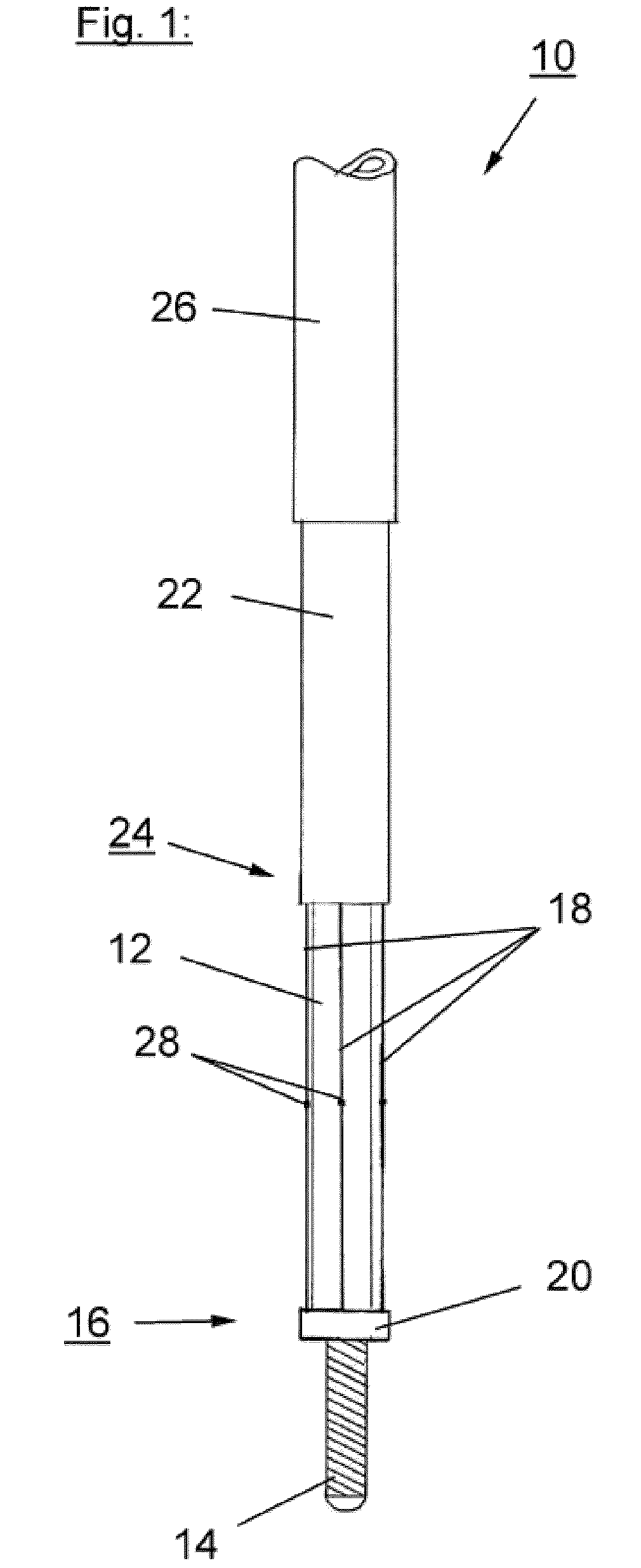
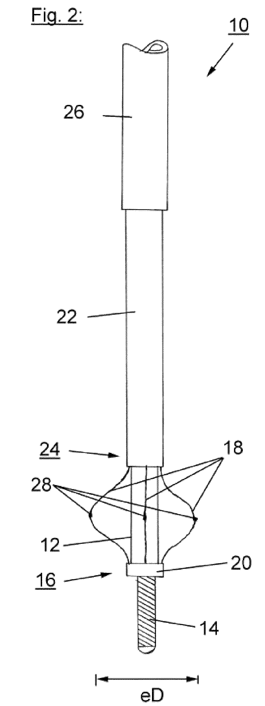
[0027]Referring now to FIG. 1, scoring catheter 10 generally includes an elongated flexible catheter body 12 having a distal end 16 and a proximal end (not shown). The catheter body 12 comprises a lumen for guiding a guide wire 14. A scoring element comprising four scoring wires 18 is positioned at said distal end 16 of the catheter body 12. The scoring wires are fixed to the distal end 16 of the catheter body 12 by a connecting element 20. The proximal end of the scoring wires 18 are fixed to the distal end 24 of a tube 22. The tube 22 is movable over and along the catheter body 12 and therefore functions as a push-tube. The scoring catheter 10 as shown in FIG. 1 further comprises a sheath 26 which can be moved over the tube 22 and a scoring element comprising the scoring wires 18. FIG. 1 shows the scoring element with the scoring wires 18 in a contracted state when positioned near the catheter body 12. Further, it can be seen that according to this embodiment of the catheter 10 t...

second embodiment

[0029]Referring now to FIG. 3, the scoring catheter 110 will be described. As can be seen, in this case the sheath 26 is replaced by a balloon catheter comprising a balloon 130 and a balloon tube 132. The balloon tube 132 or delivery catheter may have lumen or tubes in a coaxial or co-linear orientation with the longitudinal axis of the catheter body 112 and the pushing tube 122. The balloon catheter 132 will be used after the scoring procedure of the heart valves for post-dilatation of the scored heart valves. In the shown embodiment the distal end of the balloon catheter is fixed to the distal end 124 of the pushing tube 122. It is also possible that the balloon catheter comprising the balloon 130 and the balloon 130 is movable over the tube 122. The catheter 110 comprises a scoring element comprising four scoring wires 118. The scoring element is shown in a contracted state positioned near the catheter body 112. The distal end of the scoring element and the scoring wires 118, res...

third embodiment

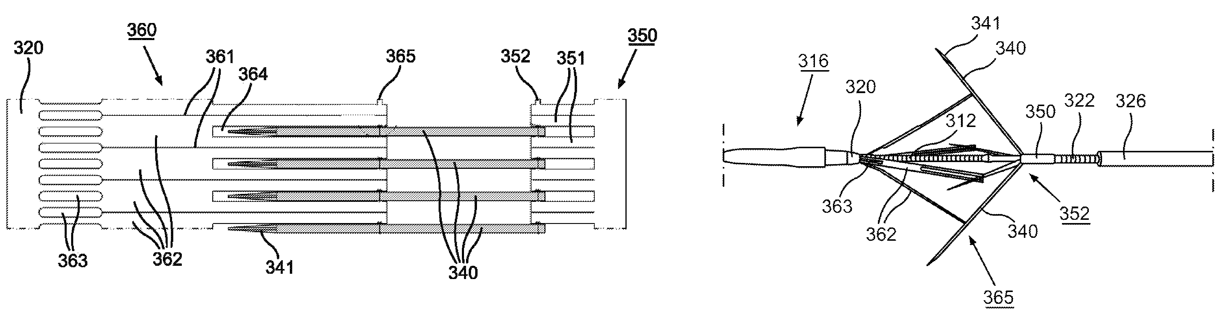
[0030]Referring now to FIG. 4, a scoring catheter 210 according to the invention is shown. The scoring catheter 210 comprises an elongated catheter body 212 with a distal end 216 and a proximal end (not shown). A scoring element comprising four scoring wires 218 is positioned at the distal end 216. The distal ends of the scoring wires 218 are connected to a connecting element 220 at the distal end 216 of the catheter body 212. The proximal end of the scoring wires 218 are connected to the distal end 224 of tube 222. By pushing the tube 222 into the distal direction the scoring element comprising the scoring wires 218 will be expanded. The scoring catheter 210 further comprises a balloon catheter comprising a balloon 230 and a balloon tube or delivery catheter 232. The balloon catheter is positioned between outer surface of the catheter body 212 and the inner surface of tube 222. The balloon 230 is placed under or in the scoring element. FIG. 4 shows the scoring element in a contract...


PUM


Abstract

The present invention provides a valvuloplasty catheter which has a scoring element at its distal part to score stenotic, calcified heart valves in radial direction and to make the single valve flaps / leaflets work again. In addition to this, the device could comprise an attached balloon to post-dilate the valve after the scoring procedure. To reduce a future recalcification, the scoring element and / or the balloon have a pharmacologic coating on their outer surface.

Description

CROSS REFERENCE TO RELATED APPLICATION[0001]This application is related to and claims priority from earlier filed provisional patent application Ser. No. 61 / 060,183, filed Jun. 10, 2008, the entire contents thereof is incorporated herein by reference.BACKGROUND OF THE INVENTION[0002]Balloon valvuloplasty is a procedure in which a narrowed heart valve is mechanically stretched using a procedure that does not require open heart surgery. Balloon valvuloplasty is ineffective as it mechanically forces the dilatation of the valve by stretching the orifice. Several studies have demonstrated that the lumen gain is small and restenosis rates at 6 months are exceedingly high (70% to 90%). There are four valves in the heart, which are located either at the boundary between the atria and the ventricles (tricuspid and mitral valves) or at the exit of the heart (aortic and pulmonary valves). The valves open and close to regulate the blood flow from one chamber to the next. They are vital to the e...

Claims


Application Information

Patent Timeline
Patent Type & Authority Patents(United States)
IPC IPC(8): A61B17/32
CPCA61B17/320725A61B2017/22098
Inventor GRANADA, JUAN F.SAUERTEIG, KNUT
Owner BAVARIA MEDIZIN TECH
Why Eureka
Try Eureka