[0006]The present invention provides improved medical apparatus and methods for the treatment of diseased heart valves, namely heart valves with stenosed regions. The stenosed regions will often include areas of calcified, fibrotic, or otherwise hardened tissue or other stenotic material of the type which can be difficult to dilate using conventional coronary
angioplasty balloons. The methods and scoring catheters will find their greatest use in treatment of
heart valve stenosis, but may also find use in treatment of the arterial, venous and / or
peripheral vasculature, treatment of small vessels and / or vessel bifurcations that will not be stented, and treatment of ostial lesions. The present invention provides improved medical apparatus which are able to
score a narrowed valve in an organized fashion, therefore could serve as a “stand-alone” device or primary therapy. Further it is possible to
score a narrowed valve in an organized fashion, and serve as a primary therapy device if coupled with a
balloon dilatation device including a
drug eluting balloon. The inventive apparatus are able to serve as an ancillary device permitting better crossing for a
percutaneous valve (PV) and to serve as an ancillary device permitting better control, positioning and
visualization for percutaneous valve (PV) placement. Further the present apparatus are able to serve as an ancillary device permitting better valve anchoring and
apposition following deployment of a percutaneous valve (PV) thus improving short term and long-term peri-valvular leaks.
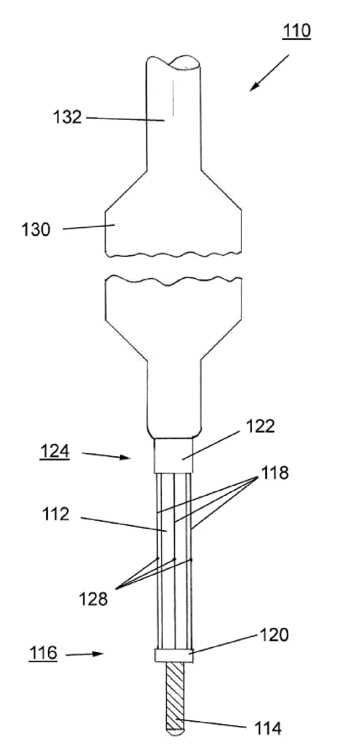
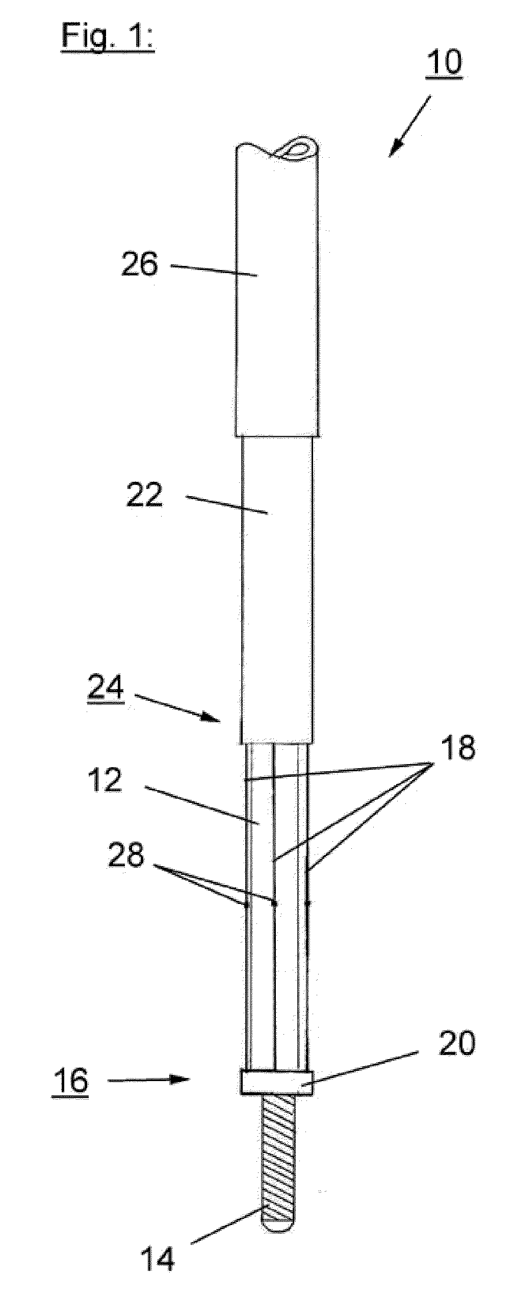
[0008]It is believed that the inventive scoring
catheter will provide improved results in the treatment of diseased heart valves. Therefore, the scoring
catheter is brought through the
heart valve to be treated, so that the scoring element of the catheter is positioned behind / beyond or at the level of the valve. After bringing the scoring element to said expanded state, said scoring element will be deployed or expanded at the level of said heart valve thereby scoring and re-opening said heart valve. The scoring element slits or dissects for example the calcified valve to a certain degree providing a controlled opening for the
insertion of a second device such as a dilatation balloon, a percutaneous valve or other ancillary devices.
[0010]According to further preferred embodiments of the present invention at least a portion of said scoring element or said scoring wire is covered by a movable sheath. The sheath can protect the vessels in the vicinity of the catheter against unintended cuts or injuries caused by the scoring element during introduction of the catheter into the body, in particular into the region of the heart flap to be treated. Usually said scoring element is made of a
metal, a
metal alloy, a
polymer, a
ceramic, or any combination of these materials. Usually the scoring element is made of Nitinol, stainless steel or
cobalt chromium. It is further possible that at least a portion of said scoring element is physically or chemically modifiable (heat,
radiation, chemical or other sources). Typically such a scoring element is heated by RF
induction heating. Also, it is possible that sensors can be attached to the tip of the catheter in order to diagnose the severity of the narrowed valve as well as to improve the safety of the device by recognizing tissue contact. Also, the scoring device may be used to deliver agents to the diseased valve such as drugs, genes, viral vectors or others. According to further preferred embodiments of the present invention the scoring catheter comprises a scoring element or scoring wire which is at least partly coated or is capable of delivering drugs or compounds. Typically said
drug prevents or reduces adverse and inflammatory effects and / or the
restenosis of said treated heart valves. It is further possible that at least a portion of said scoring element or said scoring wire extends in a direction parallel to and / or at an angle to that of the longitudinal axis of said catheter. But it is also possible that at least a portion of said scoring element or said scoring wire is arranged helically, circumferentially, or in a serpentine pattern over said catheter body. In a further preferred embodiment of the present invention said scoring element comprises an
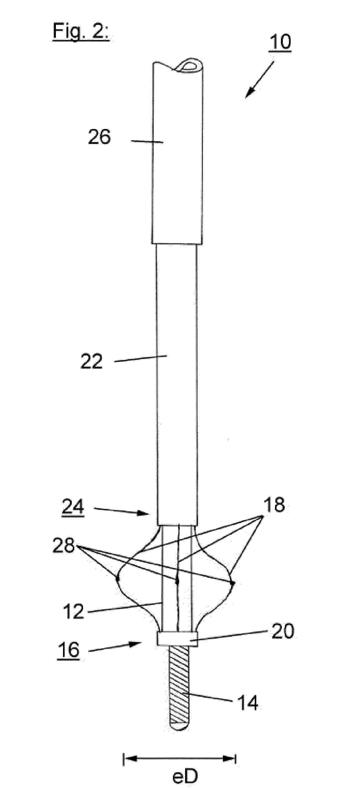
expandable cage structure. Specifically, the
cutting device could be assembled with a distal cage or centering device such as a balloon to improve the stability of the device and also serve as a guidance tool for the percutaneous
aortic valve placement.
[0011]In other preferred embodiments of the present invention the scoring catheter comprises at least one expandable balloon to dilate the heart valve after a scoring procedure. For example, the balloon is positioned proximal to said scoring element. But it is also possible that said balloon is positioned within or inside said scoring element. If the balloon is positioned within said scoring element, the scoring element could be not fixed to the surface of said balloon and the scoring element and the balloon are expandable independently from each other. It is also possible that said scoring element is fixed to the surface of said balloon and the expansion of said scoring element is accomplished by the expansion of said balloon. Further it is possible that said balloon is positioned over said scoring element which means that in this case the balloon could be moved over the scoring element after the scoring of the heart valve has been accomplished. Typically, the balloon is non- or semi-compliant. It is also possible that said balloon is at least partly coated with a
drug agent. Said drug usually prevents or reduces adverse and inflammatory effects and / or the
restenosis of said treated heart valves. It is further possible that said balloon has a rounded, triangular, multiangular, or cube-like shape. For such an inventive catheter it is possible that after the scoring treatment the catheter is again brought through the heart valve and the balloon will be inflated to dilate the narrowed heart valve.
[0013]In a preferred embodiment the inventive method further comprises the further step of positioning a balloon in the region of the scored heart valve and expanding the balloon to dilate the scored heart valve. It is possible that the step of expanding the scoring element includes the step of expanding a balloon which is positioned within said scoring element. It is further possible that said scoring element and / or said balloon is / are at least partly coated with a
drug compound. Said drug prevents or reduces adverse and inflammatory effects and / or the restenosis of said treated heart valves. It is believed that the inventive method is most useful in treating the narrowing of the heart valves. The inventive method uses a scoring catheter as described in the above. Also the balloon can be part of the catheter, not necessarily within the scoring component.
[0014]In a third aspect of the present invention the scoring catheter as described in the above is used in a balloon valvuloplasty. Another option is to have two devices. Just the scoring catheter, that runs through a PTA catheter. The PTA catheter's specific
advantage is that there is a large inner
diameter of a lumen, through which the scoring catheter runs easily. The scoring catheter can be used for all diameters, but the balloon would need to fit exactly to the needed
diameter of the heart valve (like an
endoscope). Furthermore, safety features may be added such as a proximal protection device. E.g. an additional basket is built in to protect from distal
embolization right after
cutting the tissue.

