NMR spectrometer with flowthrough sample container

Active Publication Date: 2006-05-04
BRUKER BIOSPIN
View PDF10 Cites 11 Cited by
  • Summary
  • Abstract
  • Description
  • Claims
  • Application Information

AI Technical Summary

Benefits of technology

[0012] A probe according to the present invention may have an inner surface that provides a fluid-tight seal between the components housed in the probe and a probe channel within which the sample container may be located. The surface of the probe that faces the probe channel may also be a continuous, smooth surface, such as a cylindrical surface, that allows easy flushing of the probe channel. As suc

Problems solved by technology

This process of testing one sample tube at a time is effective, but is highly laborious and time-

Method used


Image

  • NMR spectrometer with flowthrough sample container
  • NMR spectrometer with flowthrough sample container
  • NMR spectrometer with flowthrough sample container

Examples


Embodiment Construction

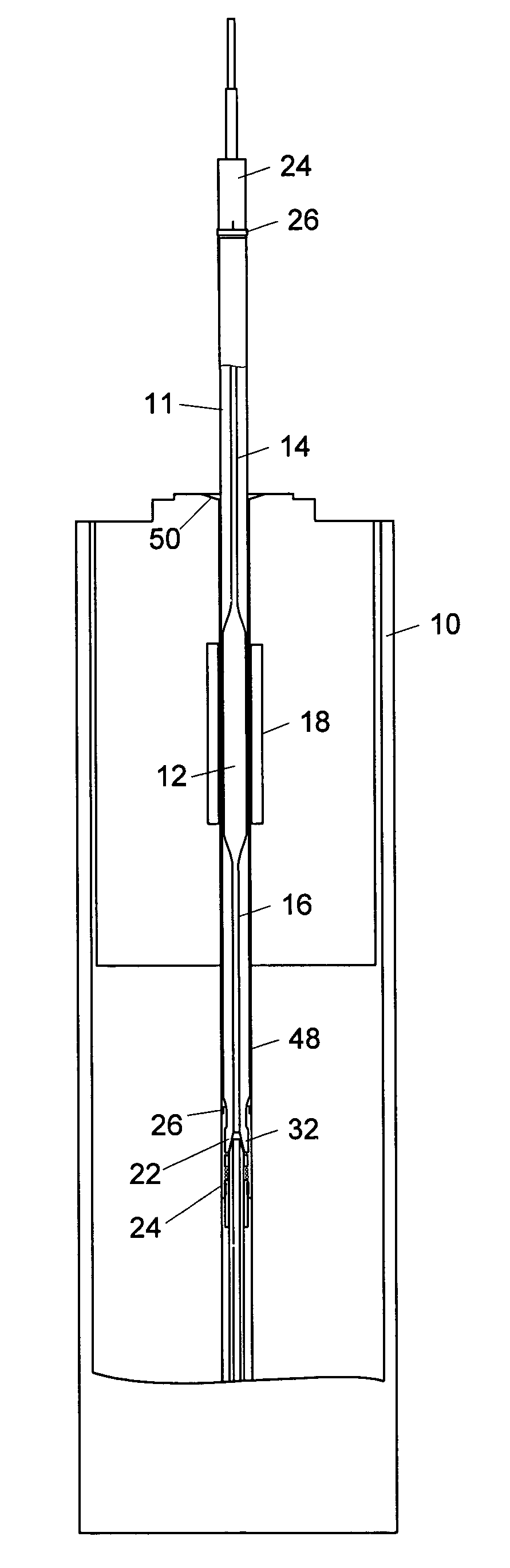
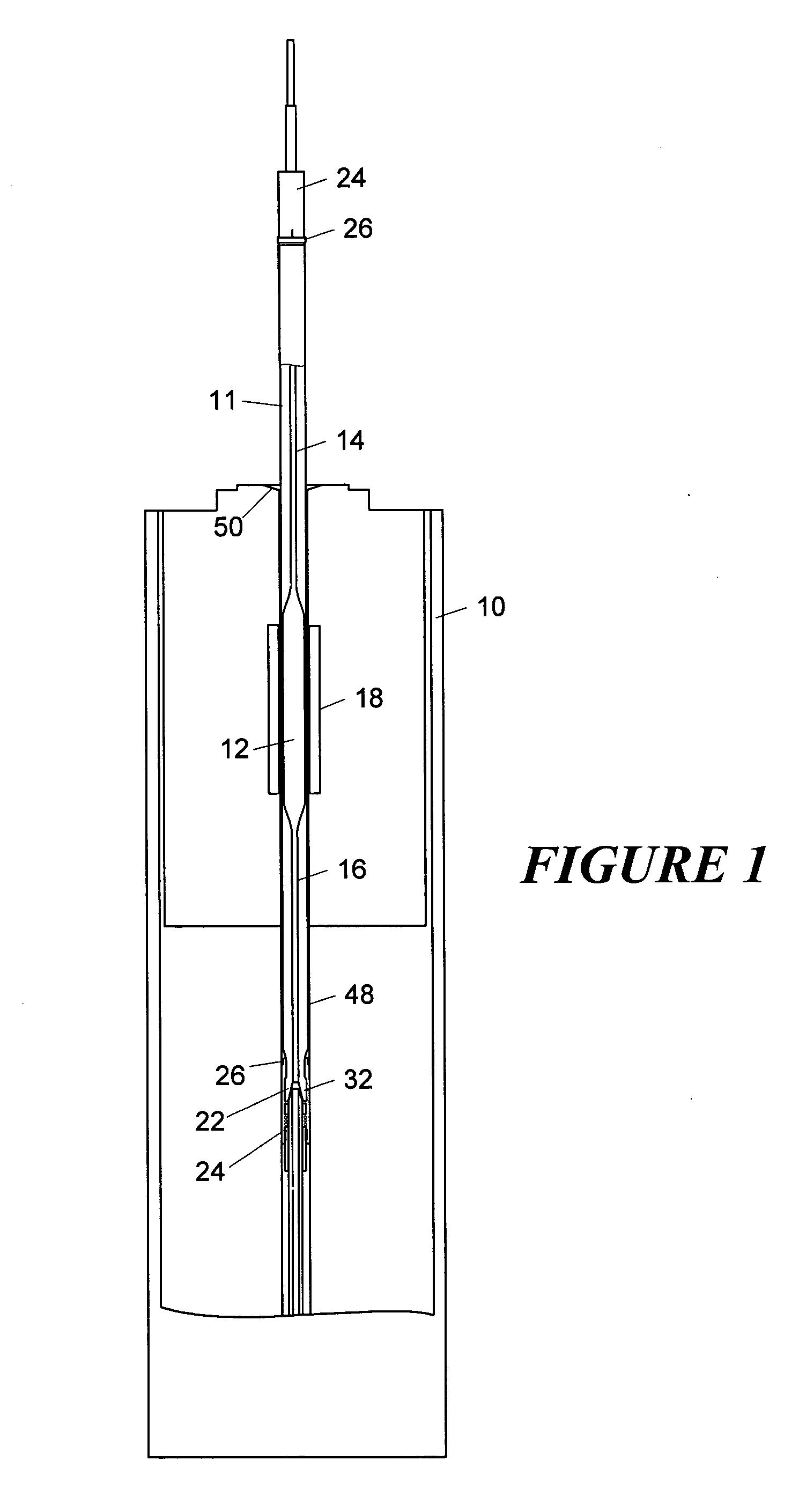
[0026] Shown in FIG. 1 is a portion of an NMR probe 10 according to the present invention, with a cutaway region showing a flow cell apparatus inside. The sample chamber 12 of the flow cell 11 comprises a cylindrical glass tube with an inner diameter that is tapered at either end of the sample chamber. The tapered ends of the sample chamber 12 reduce the diameter of the fluid space at either end of the sample tube to a capillary tube dimension, and these narrow pathways 14, 16 allow fluid flow into and out of the sample chamber 12. An outer shape of the flow cell is cylindrical, extending above and below the sample chamber 12. Within the probe 10, located very closely around the outside of the flow cell, is an RF coil 18 that provides the NMR RF pulse for inducing an NMR response from a sample fluid within the sample chamber. As shown, the thin wall of the sample chamber allows the RF coil to be in close proximity to the sample fluid, thereby maintaining a very large filling factor,...


PUM


Abstract

A flow-through sample container, or flow cell, according to the present invention resides with the channel of magnetic resonance probe without being fixed thereto. The flow cell is removable from the spectrometer while leaving the probe in place, allowing easy cleaning of the probe channel and replacement of the flow cell. An insertion tool that houses the flow cell may be used to safely introduce it to the probe. Input and output capillaries serve as fluid pathways for fluid samples entering and leaving the flow cell, respectively. These capillaries may be connected to the flow cell with a manually operable connector, allowing easy disconnection of the flow cell from the input and output conduit. The capillaries enter through different ends of the spectrometer bore, so that the fluid samples flow enter one end of the spectrometer and exit through the other.

Description

FIELD OF THE INVENTION [0001] This invention relates generally to the field of nuclear magnetic resonance (NMR) spectroscopy and, more particularly, to an NMR spectrometer in which a sample material may flow into and out of a sample holder while it is positioned in the spectrometer. BACKGROUND OF THE INVENTION [0002] In the field of NMR spectroscopy, a sample is surrounded by an NMR probe that consists of a radio frequency (RF) coil tuned to generate a field at a desired excitation frequency and receive a return NMR signal. The spectrometer typically consists of a large magnet that generates a static magnetic field, and that surrounds a sample region of the spectrometer. A sample is located in a discrete sample tube and introduced to the sample region of a probe assembly. The probe assembly includes a housing that fits within the magnet bore, and that contains the RF coil. For a probe that uses a single RF coil, the coil typically surrounds the sample tube when the sample is introdu...

Claims


Application Information

Patent Timeline
IPC IPC(8): G01V3/00
CPCG01R33/307
Inventor RINDLISBACHER, MARTINMAAS, WERNER E.
Owner BRUKER BIOSPIN
Why Eureka
Try Eureka