Gas mask and breathing equipment with a compressor

a compressor and gas mask technology, applied in the field of gas masks and breathing equipment with compressors, can solve the problems of reducing the operating time of the gas mask and breathing equipment, requiring a relatively high flow of gas, and requiring the user to leave the mission site prematurely, so as to facilitate the flushing out of carbon dioxide and reduce the speed of the compressor and consequently the effect of power consumption

Inactive Publication Date: 2005-05-24
DRAGER SAFETY
View PDF13 Cites 24 Cited by
  • Summary
  • Abstract
  • Description
  • Claims
  • Application Information

AI Technical Summary

Benefits of technology

[0007]The advantage of the present invention is essentially that an air channel is formed for the breathing air by an inner wall extending along the visor, through which air channel the breathing air purposefully reaches the mouth area of the user of the device via gas discharge openings. The breathing gas expired during the phase of expiration, which is loaded with carbon dioxide, can be flushed out by the direct flow in the mouth area directly via the air discharge opening. Due to the use of a separate air channel for supplying the breathing gas in the area of the visor, the volume of the chamber between the face of the user of the device and the inner wall can be limited to the smallest possible dead space, which additionally facilitates the flushing out of the carbon dioxide. The speed of the compressor and consequently the power consumption can be reduced due to the improved flushing out of carbon dioxide.
[0008]The flushing out of the chamber is improved by additional gas discharge openings in the lateral area of the inner wall. These additional gas discharge openings may extend over the entire lateral area of the inner wall or only over part of the lateral area. There is no increase in the local cooling and draft is minimized due to the distribution of the gas discharge openings.
[0009]The gas is advantageously fed in on the top side of the air channel. The direction of flow within the air channel is now from the eye area to the mouth area of the user of the device.
[0010]As an alternative, the gas may also be fed in symmetrically via the lateral areas of the air chamber or via the underside.
[0011]The location of the gas feed depends on the air delivery means being used.
[0012]If the visor is used in conjunction with a safety helmet and a blower as an air delivery means, the gas can be fed in on the top side of the air channel. Gas feed via the lateral surfaces or the underside of the air channel is expedient in conjunction with a compressed gas source, for example, a compressed gas cylinder.

Problems solved by technology

The drawback of the prior-art gas mask and breathing equipment is that a comparatively high breathing gas flow is needed during the phase of expiration in order to flush the expired carbon dioxide out of the chamber.
The electric power needed to drive the blower, which is supplied by a battery or a battery pack in portable devices, has an adverse effect on the operating time of the gas mask and breathing equipment, so that the user of the device must leave the site of the mission prematurely.

Method used


Image

  • Gas mask and breathing equipment with a compressor
  • Gas mask and breathing equipment with a compressor
  • Gas mask and breathing equipment with a compressor

Examples


Embodiment Construction

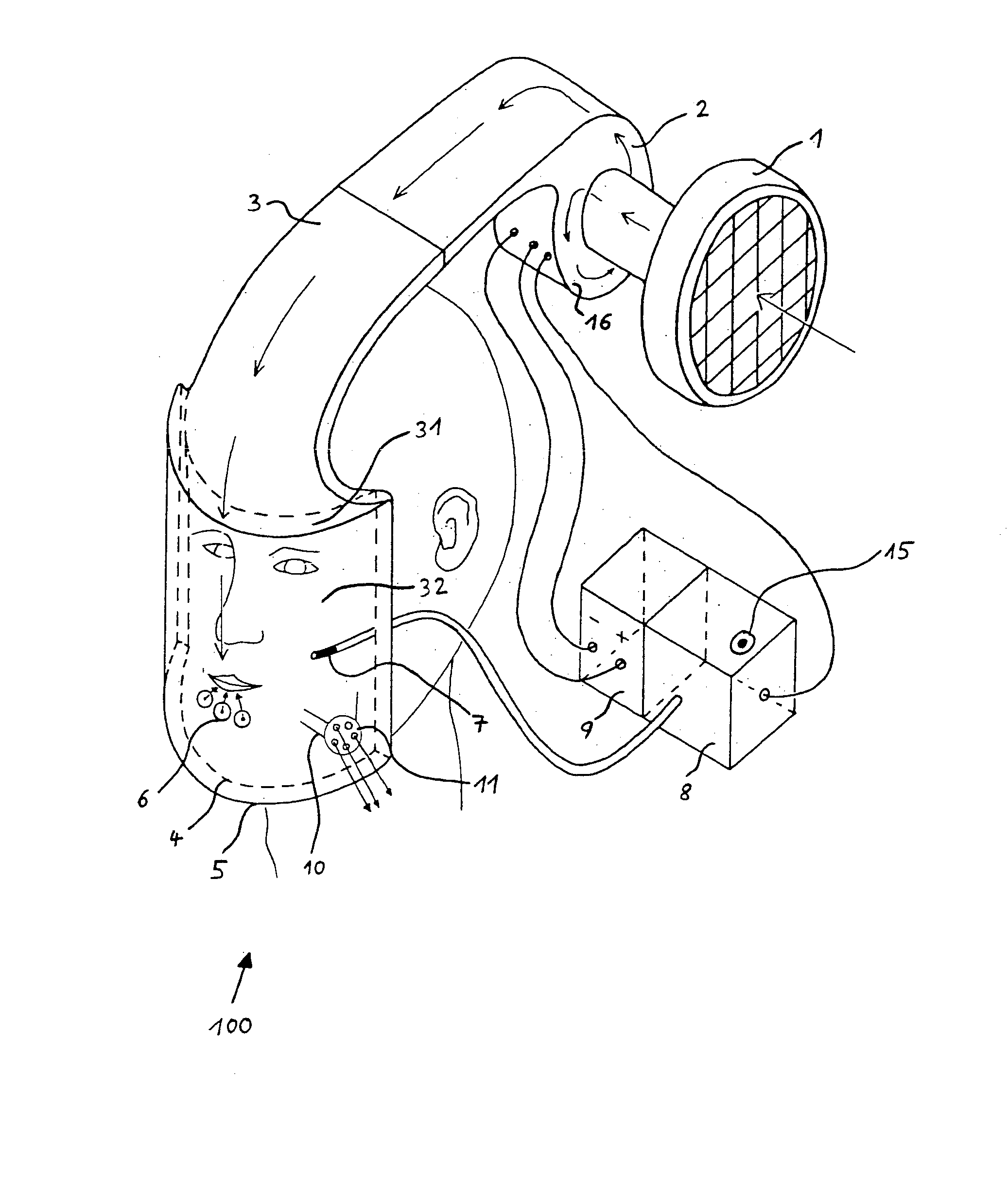
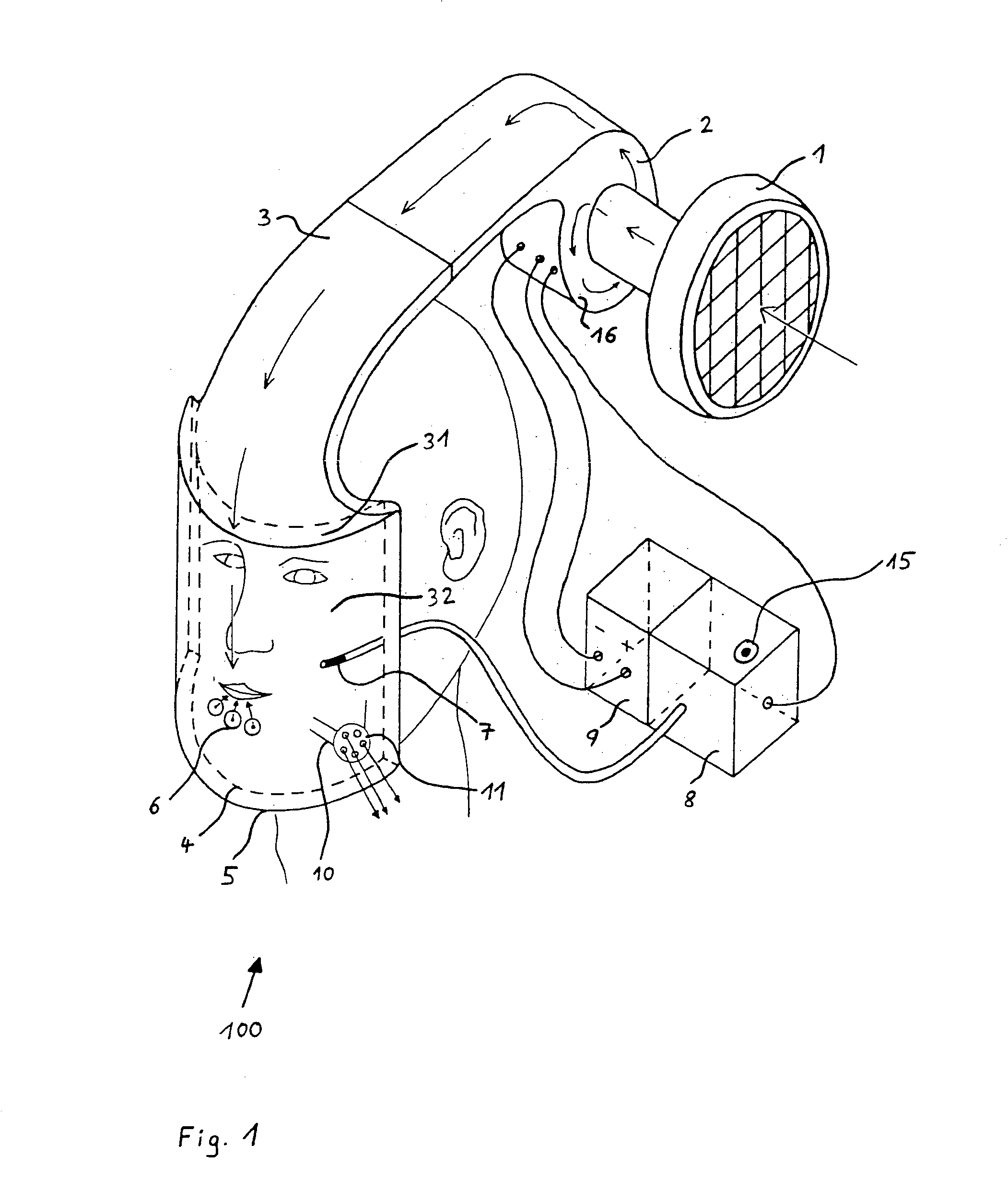
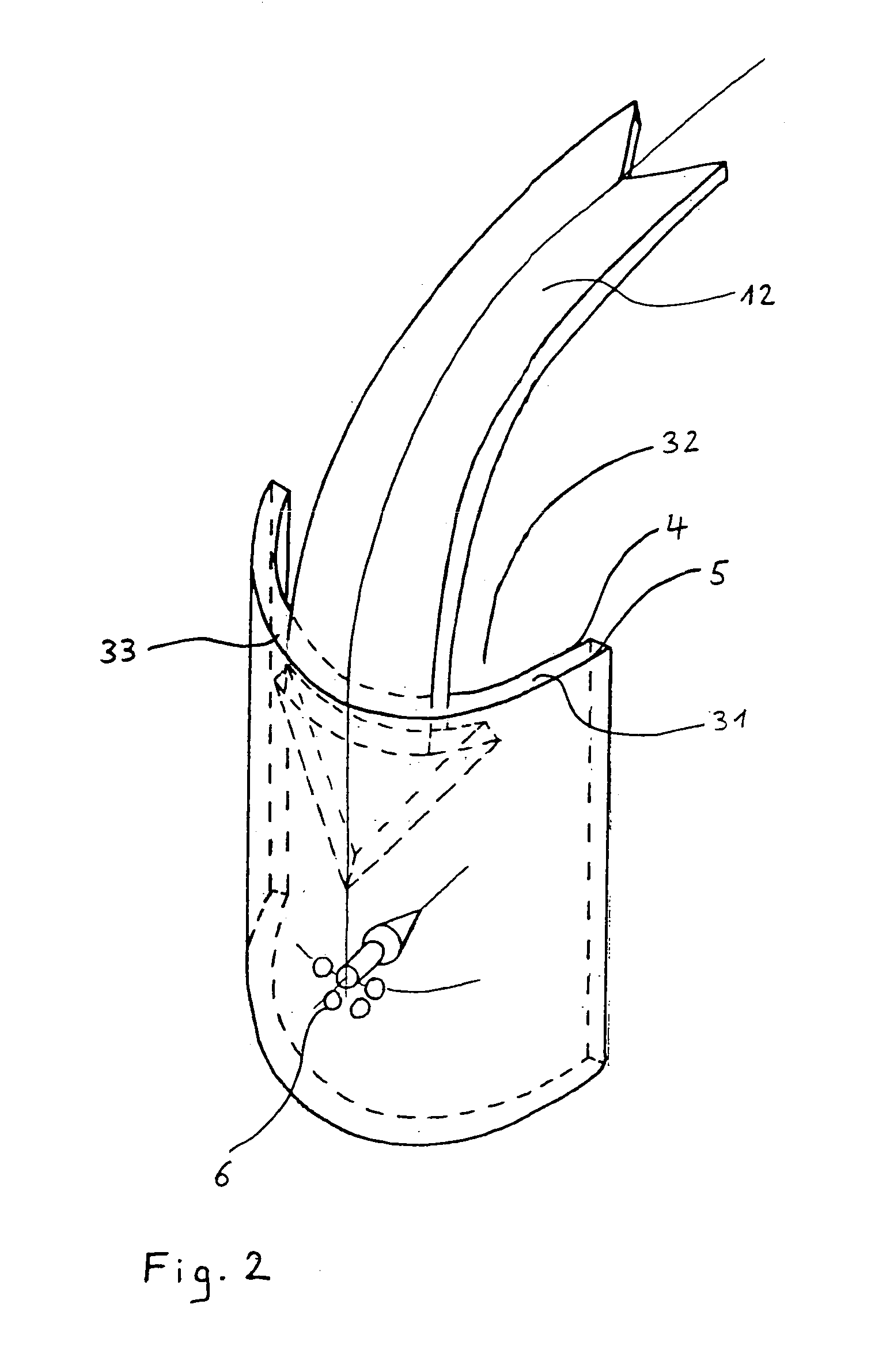
[0024]FIG. 1 schematically shows a gas mask and associated breathing equipment 100 according to the present invention. Ambient air is drawn in via a filter 1 by means of a radial flow compressor 2 (the design of the flow compressor 2 may be in accordance with features disclosed in one or more of U.S. Pat. Nos. 6,651,657; 6,474,960; 6,422,237; and 6,418,927 and U.S. application Ser. No. 10 / 247,087, filed: Sep. 19, 2002; Ser. No. 09 / 823,794, filed: Mar. 30, 2001, the contents of each of which are hereby incorporated by reference). The flow compressor delivers the air into an air channel 31 through an air guide channel 3. The air channel 31 is limited by a curved visor 5 and an inner wall 4 extending in parallel thereto. The circumferential contour of the visor 5 and the inner wall 4 is sealed, so that the breathing air flowing into the air channel 31 can be discharged into the area of the mouth of a user of the device only via gas discharge openings 6 located at the inner wall 4. Toge...


PUM


Abstract

A gas mask and breathing equipment is provided including a compressor. The gas mask and breathing equipment provides good flushing out of the carbon dioxide during the phase of expiration with the lowest possible compressor output. An air channel (31) is formed by the visor (5) and an inner wall (4) extending in parallel to the visor and is provided in the area of the visor (5). The air is discharged through gas discharge openings (6) at the inner wall (4).

Description

CROSS REFERENCE TO RELATED APPLICATIONS[0001]This application claims the benefit of priority under 35 U.S.C. § 119 of German patent application DE 103 32 899 filed Jul. 19, 2003, the entire contents of which are incorporated herein by reference.FIELD OF THE INVENTION[0002]The present invention pertains to a gas mask and breathing equipment with a compressor.BACKGROUND OF THE INVENTION[0003]A gas mask and breathing equipment of the type has become known from GB 2 058 577 A. A safety helmet with a transparent visor is located at the head of a user of the device. A blower draws in ambient air via a filter and delivers it via an air channel, which extends on the inner side of the safety helmet from the nape area to the face. The breathing air then flows on the inner side of the visor in the direction of the eye area to the area of the mouth and enters the environment via an expiration valve on the underside of the visor. The visor is in contact with the face of the user of the device v...

Claims


Application Information

Patent Timeline
Patent Type & Authority Patents(United States)
IPC IPC(8): A62B18/00
CPCA62B18/006A62B18/003
Inventor LUKAS, HEINER
Owner DRAGER SAFETY
Why Eureka
Try Eureka