Bridge plug for fracturing of casing pipe

A fracturing and casing technology, which is applied in the direction of production fluid, wellbore/well parts, earthwork drilling and production, etc. It can solve the problems of high operating cost, difficult drilling and grinding, and high risk of drilling and grinding, so as to avoid drilling and grinding operation, and the effect of improving reliability

Inactive Publication Date: 2015-10-21
PETROCHINA CO LTD
View PDF12 Cites 12 Cited by
  • Summary
  • Abstract
  • Description
  • Claims
  • Application Information

AI Technical Summary

Problems solved by technology

However, after pressing, it needs to be drilled and removed before normal production. Due to the use of high-strength metal materials for slips, it is difficult to drill and grind, it is difficult to return debris, high operating costs and high risks of drilling and grinding operations still exist.

Method used


Image

  • Bridge plug for fracturing of casing pipe

Examples


Embodiment 1

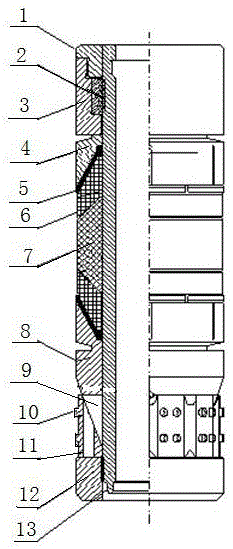
[0025] This embodiment provides a bridge plug for casing fracturing, such as figure 1 As shown, it includes a central rod 13 and an upper joint 1 and a lower joint 12 respectively connected to the upper and lower ends of the central rod 13. The middle part of the central rod 13 is covered with a cylindrical long rubber tube 7 and a short rubber tube 6. The upper and lower ends of the long rubber tube 7 are respectively symmetrically provided with short rubber tubes 6 in turn, and the upper and lower parts of the central rod 13 are respectively covered with an upper support sleeve 4 and a lower support sleeve 8, and the upper support sleeve 4 and the lower support sleeve 8 are respectively fixed. There is a rubber cartridge seat 5, and the short rubber cartridges 6 located at the upper and lower ends of the long rubber cartridge 7 are installed on the rubber cartridge seat 5;

[0026] A seat ring 3 is arranged between the upper support sleeve 4 and the upper joint 1, and the up...

Embodiment 2

[0031] On the basis of Embodiment 1, a locking mechanism is also provided in this embodiment. In this embodiment, the inner wall of the seat ring 3 is stepped, and a locking block 2 is arranged on the step, and the locking block 2 is sleeved on the central rod 13 Above, the upper and lower ends of the locking block 2 are respectively limited by the steps of the upper joint 1 and the inner wall of the seat ring 3 .

[0032] The locking block 2 is a cylindrical structure, and the locking block 2 and the central rod 13 are connected by a horse-tooth button.

[0033] The locking mechanism of this embodiment adopts the form of horsetooth buckle connection to form unidirectional stress. Here, the horsetooth buckle connection adopts the form of two positive and negative horsetooth buckles. The tooth buckle, the locking block 2 is a positive horse tooth buckle, so that the seat ring 3 and the upper support sleeve 4 are only subjected to downward stress and can only move downward, prev...

Embodiment 3

[0035] On the basis of Embodiment 1 and Embodiment 2, in this embodiment, there are at least three guide pins 9, which are evenly distributed in the circumferential direction on the lower end of the lower support sleeve 8; Four anchor flukes 10 are arranged on the slips.

[0036] Slips 11 are composed of multiple single-piece slips, so that during the continuous upward movement along the guide pin 9 and along the lower support sleeve 8, the slips 11 will slowly break into single single-piece slips, and the single-piece slips The four flukes 10 move radially with the single slip until the flukes 10 are anchored to the inner wall of the casing.

[0037] The connecting surfaces between the upper support sleeve 4, the rubber cylinder seat 5, the short rubber cylinder 6, the long rubber cylinder 7 and the lower support sleeve 8 are slopes, and these slopes are inclined to the middle long rubber cylinder 7.

[0038] The bevel-shaped end surface setting of this embodiment can make t...


PUM


Abstract

The invention relates to a bridge plug for fracturing of a casing pipe. The bridge plug comprises a center rod, an upper connector and a lower connector. The upper connector and the lower connector are arranged at the upper end and the lower end of the center rod. The middle of the center rod is sleeved with a long rubber cylinder and short rubber cylinders. The upper portion and the lower portion of the center rod are sleeved with an upper supporting sleeve and a lower supporting sleeve respectively. Rubber cylinder seats are fixed to the upper supporting sleeve and the lower supporting sleeve respectively. The short rubber cylinders at the upper end and the lower end of the long rubber cylinder are installed on the rubber cylinder seats. A seat ring is arranged between the upper supporting sleeve and the upper connector, and the upper end and the lower end of the seat ring abut against the upper connector and the upper supporting sleeve respectively. A slip is arranged between the lower supporting sleeve and the lower connector and is provided with an anchor jaw. According to the bridge plug which is provided with the slip and a locking mechanism and used for fracturing of the casing pipe, the reliability of the bridge plug can be ensured, degradable materials are adopted, and degrading can be conducted as time goes by when certain shaft conditions are reached. The bridge plug for fracturing of the casing pipe has the advantages of being high in pressure bearing capability, free of plug drilling and large in diameter and can be used for transformation of multiple sections of a reservoir of a highly-deviated well and a horizontal well and put into production rapidly.

Description

technical field [0001] The invention belongs to the technical field of high-inclination and multi-stage reconstruction of horizontal wells in oil and gas fields, and in particular relates to a bridge plug for casing fracturing. Background technique [0002] The role of the bridge plug is to seal the oil and gas well, which has the characteristics of less construction procedures, short cycle and accurate sealing position. Use cables or pipe strings to transport it to the predetermined position in the wellbore, and the thrust generated by gunpowder combustion, hydraulic or mechanical setting tools acts on the upper joint, and the pulling force acts on the center rod. When the tension reaches a certain value, the tension rod breaks, and the setting tool is separated from the bridge plug. At this time, the locking device on the center rod of the bridge plug works, the slips are broken and embedded on the inner wall of the casing, the rubber tube expands and seals, and the setti...

Claims


Application Information

Patent Timeline
IPC IPC(8): E21B33/122E21B43/26
Inventor 胡相君桂捷李旭梅王效明邵媛张安康张丽娟
Owner PETROCHINA CO LTD
Why Eureka
Try Eureka