Staged fracturing construction method for long well section

A staged fracturing and construction method technology, applied in the field of fracturing construction, can solve the problems of soluble bridge plug sealing performance, great influence on dissolution performance, increase treatment measures, difficulty in lowering tools, etc., to save operating time and cost , avoid the risk of downhole operation, and avoid the effect of drilling and grinding operations

Pending Publication Date: 2022-07-12
CHINA PETROLEUM & CHEM CORP +1
View PDF0 Cites 0 Cited by
  • Summary
  • Abstract
  • Description
  • Claims
  • Application Information

AI Technical Summary

Problems solved by technology

[0003] Staged fracturing requires the use of plugging tools to reliably plug the interlayers. The single-slip bridge plug has been widely used because of its simple structure, small size, and low cost. The sealing and loss is controlled by shear pins, which are made of insoluble materials. After the bridge plug is dissolved, a large number of insoluble shear pins fall into the well, and the accumulation of the wellbore leads to complex situations such as difficulty in installing tools in the later stage. It is easy to get stuck when cleaning the plug
Moreover, there is no locking mechanism after the bridge plug is set, and the vibration during perforation after the bridge plug is set may easily cause the bridge plug to be unsealed, resulting in fracturing failure
[0004] In addition, formation temperature and formation pressure have great influence on the sealing performance and dissolution performance of soluble bridge plugs. Due to the large amount of fracturing fluid entering the formation in the early stage, the formation temperature drops and the formation temperature recovers slowly.
Therefore, due to inaccurate grasp of formation temperature and pressure, it is also easy to lead to wrong selection of soluble bridge plugs, resulting in unsealed soluble bridge plugs, too short or too long dissolution time, resulting in fracturing failure or additional follow-up treatment measures

Method used


Image

  • Staged fracturing construction method for long well section
  • Staged fracturing construction method for long well section
  • Staged fracturing construction method for long well section

Examples


Embodiment Construction

[0054] In the following description of the present invention, the orientation or positional relationship indicated by the terms "upper", "lower", "front", "rear", "left", "right", "inner", "outer", etc. is based on the attached The orientation or positional relationship shown in the figures is only for the convenience of describing the present invention and simplifying the description, and does not mean that the device must have a specific orientation. In horizontal wells, those closer to the bottom of the well are referred to as "below", and those closer to the wellhead are referred to as "above".

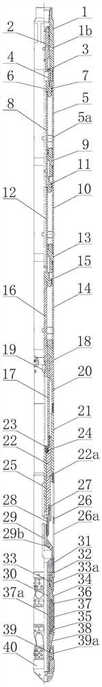
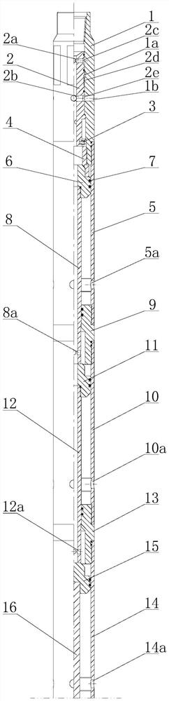
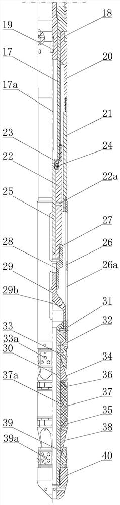
[0055] like Figure 1 to Figure 3 As shown, the plugging combined tool used in the present invention sequentially includes a slide valve, a setting driving mechanism, a pressure detection mechanism and a soluble bridge plug from top to bottom. The valve body cavity of the slide valve 1 is provided with a valve core 2; the setting drive mechanism includes an upper cylinder liner 5...


PUM


Abstract

The invention discloses a staged fracturing construction method for a long well section, which sequentially comprises the following steps of: confirming that the well cementation quality is qualified, determining the position of each oil layer, perforating and fracturing a first oil layer, drifting and scraping a setting well section above the just fractured oil layer, feeding a plugging combination tool into a well, and when the plugging combination tool reaches the setting well section, drilling and scraping the setting well section; a well bore is subjected to conventional well washing, a ball is thrown to close a bypass hole of a valve body, a setting driving mechanism is released, a well mouth is pressurized, a bridge plug is set, the well mouth continues to be pressurized, parts above the bridge plug are released, the well mouth is lifted out to read actual pressure of a stratum, a soluble ball is thrown, the soluble ball falls on an upper end opening of the just-set bridge plug, and the plugging performance of the just-set bridge plug is inspected. Perforation and fracturing are conducted on the previous oil layer, according to the measured actual stratum pressure, the bridge plug model suitable for the next section is selected, and the process is repeated till staged fracturing of all the oil layers is completed. The construction method is high in fracturing success rate, the construction cost is saved, and production of a single well is achieved in advance.

Description

technical field [0001] The invention relates to a fracturing construction method, in particular to a staged fracturing construction method for a long well section, and belongs to the technical field of oil recovery methods. Background technique [0002] Shale reservoirs are characterized by ultra-low porosity and ultra-low permeability. After drilling and completion of horizontal wells, hydraulic fracturing is required to obtain economic production. Fracturing is the injection of high-pressure, large-displacement fracturing fluid into the well through a high-pressure pump set. When the pump injection rate is greater than the absorption rate of the formation, the formation will rupture or the original tiny gap will open, forming a larger fracture. crack. With the continuous injection of liquid, the cracks that have formed extend inward. In order to prevent the fracture from re-closing after the pump is stopped, proppant is usually added to the injected liquid. After the fo...

Claims


Application Information

Patent Timeline
IPC IPC(8): E21B43/26E21B43/267E21B33/134E21B47/06
CPCE21B43/26E21B43/261E21B43/267E21B33/134E21B47/06
Inventor 颜琳娜杨鹏李巧宁
Owner CHINA PETROLEUM & CHEM CORP
Why Eureka
Try Eureka