Rail structure of high-speed rail transportation

A high-speed track and track technology, applied in tracks, roads, buildings, etc., can solve the problems of reducing the service life of track structures, poor adjustability of support methods, and affecting structural safety, so as to improve lateral stiffness, speed up production progress, and save The effect of investment

Inactive Publication Date: 2002-05-22
SHANGHAI MAGLEV TRANSPORTATION DEVELOPMENT CO LTD
View PDF0 Cites 8 Cited by
  • Summary
  • Abstract
  • Description
  • Claims
  • Application Information

AI Technical Summary

Problems solved by technology

[0005] 1. When the steel structure in the functional area and the reinforced concrete slab girder are integrally manufactured, due to the different material properties, the joint surface of the two materials is likely to cause shrinkage gaps, and under the repeated load of the train, the concrete slab girder will produce fatigue cracks and reduce the track structure. service life
[0006] 2. The connection method of the upper and lower structures is unreliable. The longitudinal temperature expansion and contraction of the slab beam will cause the concrete at the bottom of the front and rear support columns to crack. Under repeated loads, the cracks will develop and damage the steel bars in the hinge, which will affect the structural safety; The force of the connection between the tie rods is not clear, which leads to the complex force of the cement mortar cushion, and it is easy to be damaged when the longitudinal, horizontal and vertical loads act at the same time, which endangers the safety of the structure
[0007] 3. The adjustability of the support method is poor. Since the part of the tie rod between the slab girder and the supporting column has been poured in the slab girder, and the cement mortar cushion has been firmly bonded to the slab girder and the supporting column, it is necessary to chisel when adjusting the position of the rail surface structural slab girder. In addition to the structural part of the concrete, the construction is difficult and the operability is poor
[0008] 4. The lateral rigidity of the substructure is small. In order to make the side of the track structure meet the requirements of the dynamic characteristics of the system, the lateral dimension of the substructure has to be designed to be very large

Method used


Image

  • Rail structure of high-speed rail transportation
  • Rail structure of high-speed rail transportation
  • Rail structure of high-speed rail transportation

Examples


Embodiment Construction

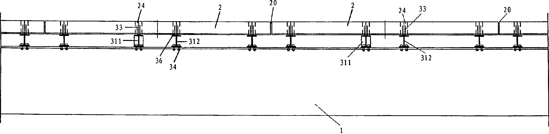
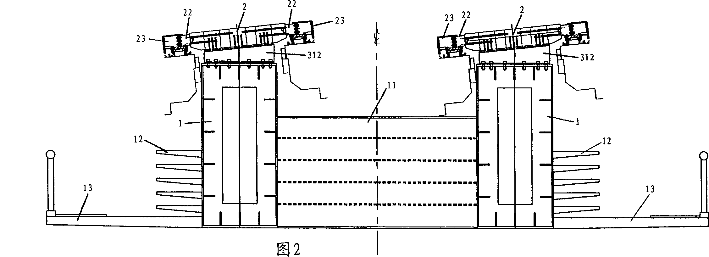
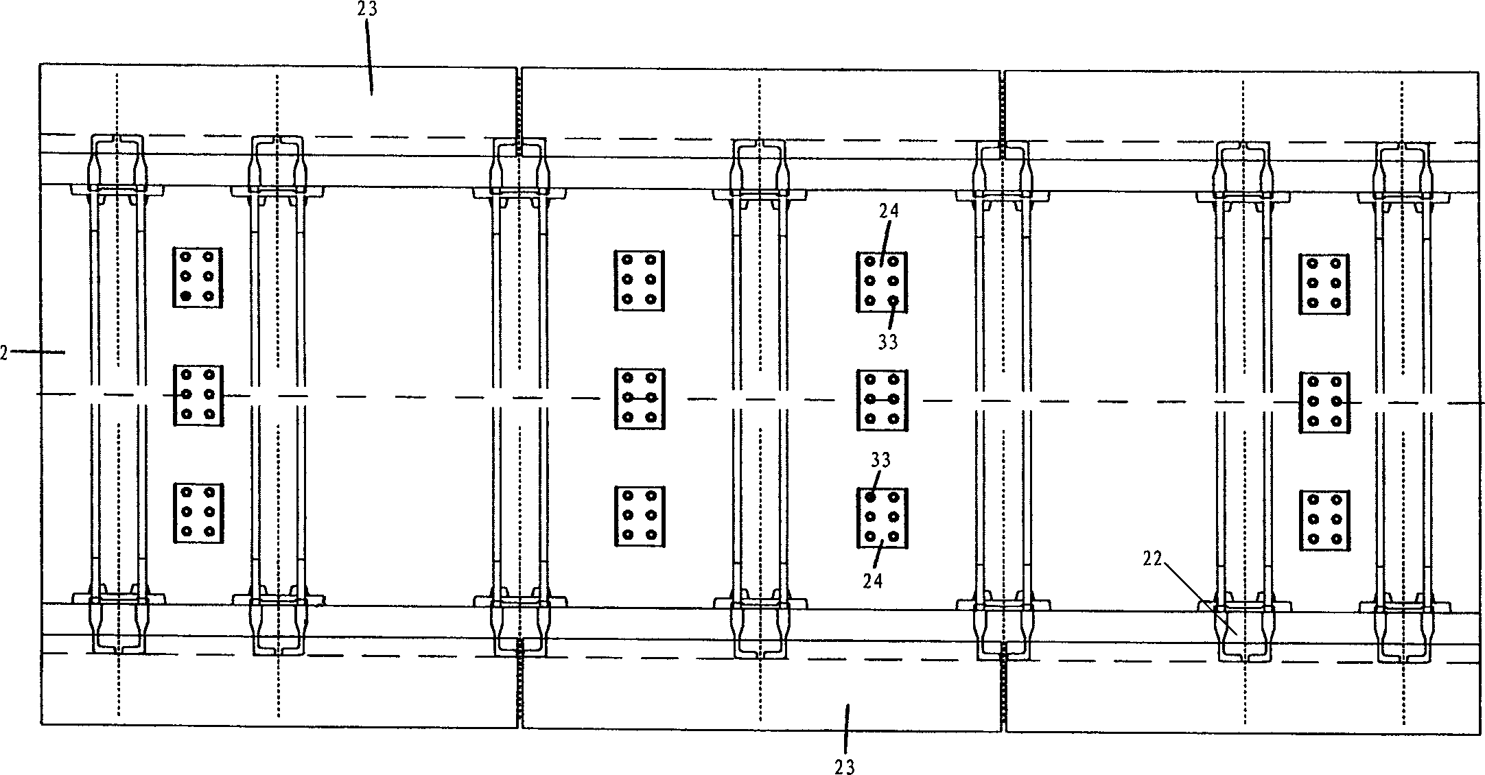
[0046] figure 1 The overall layout of the double-deck track structure of the present invention is shown in , from the elevation, the reinforced concrete slab girder 21 (hereinafter referred to as member 21) of the upper layer rail surface structure and the lower load-bearing main beam 1 are connected as a whole through a connecting mechanism 3, and the member 21 It is a small component whose length can be one to two times the length of a single functional part (3.096m). Multiple components 21 are vertically erected on the lower support structure along the line, and a certain telescopic gap 20 is left between the two components 21 to meet Longitudinal and transverse live load deformation and component temperature expansion and contraction deformation. The purpose of adopting a smaller size for the longitudinal direction of member 21 is mainly to reduce the difficulty of making and processing the upper rail surface structure. The weight of a single member 21 is relatively light,...


PUM


Abstract

The track structure for high-speed rail traffic includes lower-layer bearing main beam and upper-layer rail level member, the rail level member is made up by using function zone steel member and self-body reinforced concrete plate beam which are connected into one body by means of connecting componnet. It is characterized by that (1). the reinforced concrete plate beam is a kind of small member, severl reinforced concrete plate beams are laid on the lower-layer main beam longitudinally along the line by means of connecting mechanism, between two reinforced concrete plate beams there is a certain expansion joint, (2), the describec connecting mechanism is formed from support steel beam, welding nail, high-strength bolt and steel soleplate, the support steel beam is connected with lower-layer bearing main beamm, the welding nail of top of supper steel beam is inserted into rear funnel of reinforced concrete plate beam, after the plate beam is positioned, concrete can be cast to make connection, and (3). for double-line rail, between sides of bearing main beam the support cross beam can be added.

Description

technical field [0001] The invention relates to a track structure for high-speed rail traffic, in particular to a track structure suitable for maglev trains. Structure (reinforced concrete slab beams) combined. Background technique [0002] Maglev train is a high-speed transport system. When it is running at high speed, it has extremely high precision requirements for the supporting structure, that is, the track structure. First of all, in terms of the force characteristics of the track structure, it is required that the track structure be in the mobile vehicle, the external environment, such as temperature change, wind, etc. , its deformation and deflection should be controlled within a very small range; at the same time, there are strict restrictions on the dynamic characteristics of the track structure. The maglev train requires that the first-order natural frequency of the track structure (whether it is the longitudinal or transverse direction of the connected structure...

Claims


Application Information

Patent Timeline
Patent Type & Authority Applications(China)
IPC IPC(8): E01B25/30
CPCE01B25/305
Inventor 吴祥明吴忠
Owner SHANGHAI MAGLEV TRANSPORTATION DEVELOPMENT CO LTD
Why Eureka
Try Eureka