
Hinge mechanism

a hinge mechanism and hinge technology, applied in the field of hinge mechanisms, can solve the problems of deteriorating the rotation shaft cannot be swung, and the assembling ability of the hinge mechanism may be deteriorated, and it is difficult to view

Inactive Publication Date: 2013-04-16
MITSUBISHI ELECTRIC CORP
View PDF10 Cites 3 Cited by
  • Summary
  • Abstract
  • Description
  • Claims
  • Application Information

AI Technical Summary

Benefits of technology

[0017]According to the present invention, the shaft can be prevented from being swung under vibrating conditions by virtue of the leaf spring having the sliding friction projection that slides with pressed into contact with the base on the side opposite from the other of the click projection and the click recess across the axis of rotation.

Problems solved by technology

A hinge mechanism provided with one click projection and eliminating a resilient member 6 as shown in FIG. 6 and FIG. 7 has a problem that a clearance in the fit between a rotation shaft hole of a base and a rotation shaft causes the rotation shaft to be swung.
Thus, the assembling ability of the hinge mechanism 21 may be also deteriorated.
Consequently, there is a problem such that when the conventional hinge mechanism is used in the folding and unfolding mechanism of a vehicle-mounted monitor or the like, the protrusion is moved to swing the screen, which makes it hard to view.
Further, in addition to the fact that the hinge device has to be bulky in the axial direction thereof due to a large number of components of the device, in the event that the plate thickness of the friction member (spring washer or the like) or the spring characteristic of a spring material varies, the hinge device is different in the characteristics of the holding torque; thus, there are some cases that stable torque performance thereof is not obtained.
Furthermore, similarly to the hinge mechanism 21 discussed above, it is necessary to secure a suppression member to the end face of the shaft member by caulking while the resilient member for pressing the friction member into contact with the rotation member is being flexed, thus deteriorating the ability of the hinge mechanism to be assembled.

Method used


Image

  • Hinge mechanism
  • Hinge mechanism
  • Hinge mechanism

Examples


first embodiment

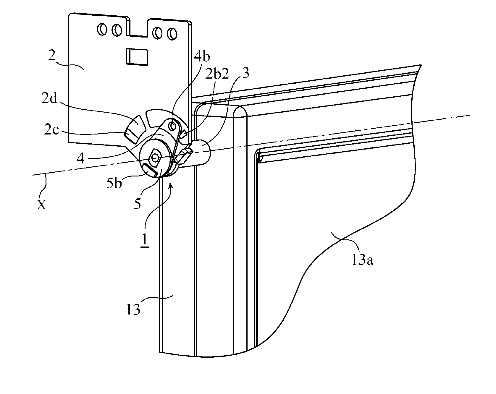
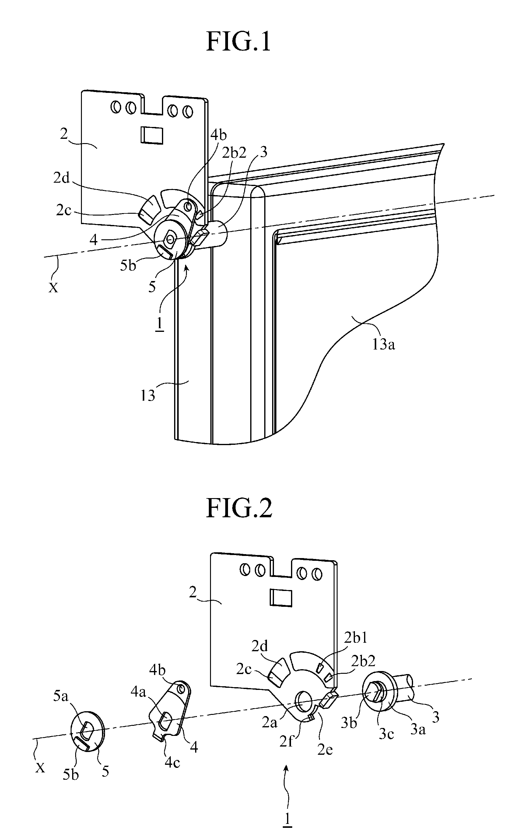
[0030]In a first embodiment of the present invention, a hinge mechanism will be explained using a case where the mechanism is used in a ceiling-mounted monitor apparatus 11 as shown in FIG. 8A to FIG. 8B by way of example. FIG. 1 is a perspective view showing an arrangement of a hinge mechanism 1 according to the first embodiment of the present invention, and FIG. 2 is an exploded perspective view thereof. Note that in the following embodiments, parts which are the same as or equivalent to the constituent elements in the prior art (FIG. 6 to FIG. 9) previously discussed are designated by similar numerals, and explanations of the parts will be omitted.

[0031]A base 2 is newly provided with a cutaway 2e formed by cutting away a portion of an edge thereof opposing a housing position determining recess 2c across a rotating central axis X, and a taper 2f is provided at a portion of the edge of the cutaway 2e.

[0032]A rotation shaft 3 is newly provided with a cylindrical section 3c having ...


PUM


Abstract

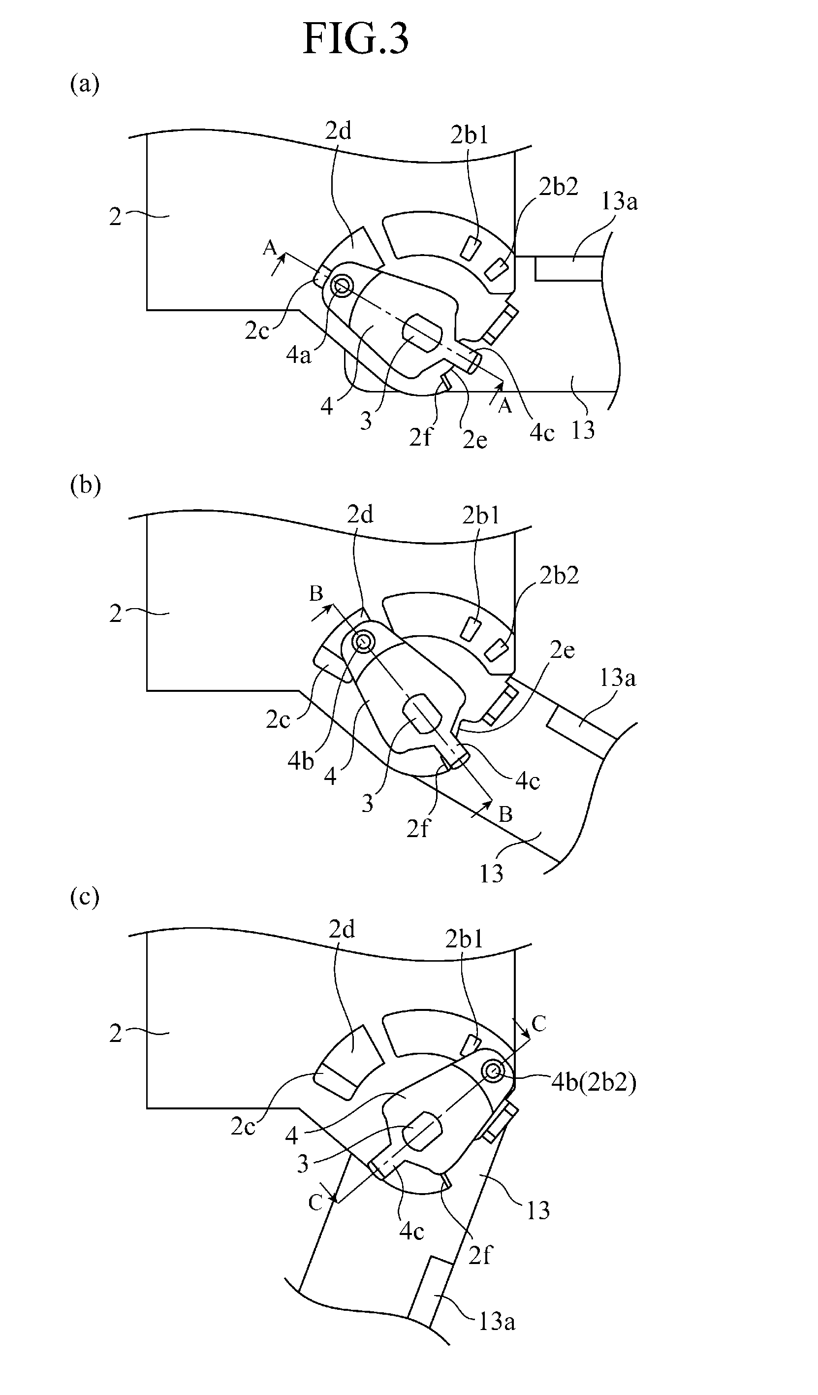
A hinge mechanism 1 includes a rotation shaft 3 connected to a monitor and serving as rotating central axis X; a base 2 pivotally supporting the shaft 3 rotatably, and having click recesses 2b1, 2b2 and a housing position determining recess 2c on a circumference centering the axis X; a plate 5 attached at the end of the shaft 3; and a leaf spring 4 located between the base 2 and plate 5, fit-in by the rotation shaft 3, and having a click projection 4b that fits in the click recesses 2b1, 2b2 and recess 2c to hold the monitor in a predetermined rotation angle position. A sliding friction projection 4c sliding with pressed into contact with the base 2 is formed on the side opposite from the click projection 4b across the axis X, while a cutaway 2e entered by the projection 4c is formed in the base 2.

Description

TECHNICAL FIELD[0001]The present invention relates to a hinge mechanism for folding and unfolding a monitor or the like.BACKGROUND ART[0002]A conventional hinge mechanism used for a vehicle-mounted monitor apparatus will be discussed with reference to FIG. 6 and FIG. 7. FIG. 6 is a perspective view showing an arrangement of a conventional hinge mechanism 21 having a click action, and FIG. 7 is an exploded perspective view thereof. The hinge mechanism 21 is arranged such that a rotation shaft 3 connected to a monitor 13 and rotating about a rotating central axis X is fit in a resilient member 6, a base 2, a leaf spring 4, and a plate 5 to be caulked.[0003]The rotation shaft 3 is provided with a flange 3a having a radius larger than that of a rotation shaft hole 2a of the base 2, and a D-cut section 3b having a radius smaller than that of the rotation shaft hole 2a and having a pair of flat faces formed symmetrically. On the other hand, the rotation shaft hole 2a to be rotatably inser...

Claims


Application Information

Patent Timeline
Patent Type & Authority Patents(United States)
IPC IPC(8): E05D11/10
CPCB60R11/0235E05D11/1057E05D7/081B60R2011/0028B60R2011/0085E05Y2900/538Y10T16/551Y10T16/5403Y10T16/54028Y10T16/558Y10T16/5385
Inventor NAGAMI, TETSURO
Owner MITSUBISHI ELECTRIC CORP
Learn More