Closable type display apparatus

a display apparatus and retractable technology, applied in the direction of hinges, candle holders, light support devices, etc., can solve the problems of affecting the image, becoming a factor of increased cost, and the type of closable display apparatus has a problem, so as to prevent the swing and eliminate the deterioration of the appearance

Inactive Publication Date: 2012-11-06
MITSUBISHI ELECTRIC CORP
View PDF18 Cites 4 Cited by
  • Summary
  • Abstract
  • Description
  • Claims
  • Application Information

AI Technical Summary

Benefits of technology

[0009]According to the present invention, the load produced in a direction axially of the rotating shaft by the vibration caused by the travel of a vehicle is arranged to be imposed also on the side of the upright section through the positioning structure. Thus, the force is distributed and thereby the bearing supporting member is prevented from being bent, which enables the display panel to be prevented from being swung. Furthermore, the clearance between the display unit and the display panel in a closed state can be maintained uniform, and thus deterioration in the appearance can be also eliminated.

Problems solved by technology

Meanwhile, this type of closable display apparatus has a problem of an influence caused by the vibration of a vehicle.
In a conventional closable type display apparatus as disclosed in Patent Document 1, a rotating shaft is held against axial displacement imposed thereon by vibration with the elastic force of a tension plate, and thus the display apparatus has a limitation to such vibration having a large amplitude as causes the swing of the display panel, which may influence the image.
Further, in the conventional structure, there is a problem that the number of man-hours increases in providing grooves along the rotating shaft, adding members for the tension plate, assembling the members, and adjusting the assembled members, and this can become a factor of increased cost.
As a result, there occurs a problem that the bearing supporting member is axially bent to cause the display panel to be swung, thus making the image hard to see.
Further, when the display panel is in a closed state, there is a problem that the clearance between the display panel and the panel housing section is not maintained uniform to deteriorate the appearance of the display apparatus.

Method used


Image

  • Closable type display apparatus
  • Closable type display apparatus
  • Closable type display apparatus

Examples


first embodiment

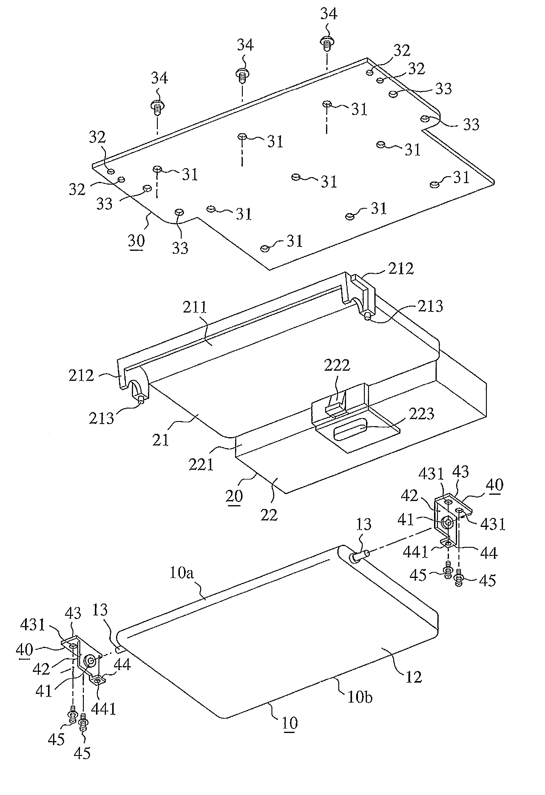
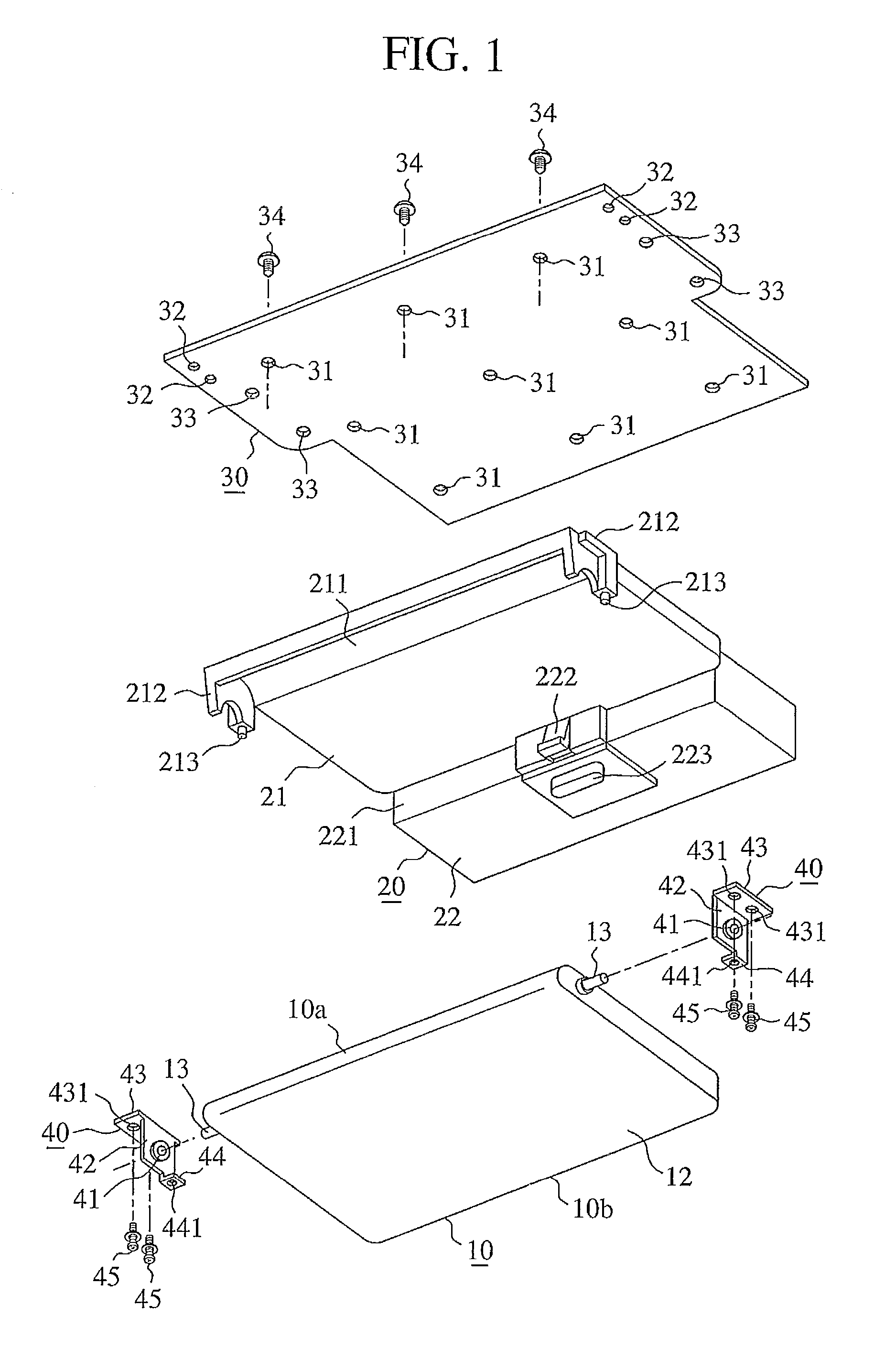
[0015]FIG. 1 is an exploded view of a closable or opening / closing type display apparatus in accordance with the first embodiment of the present invention. FIG. 2 is a perspective view showing the assembled structure of a bearing supporting member in accordance with the first embodiment of the present invention. FIG. 3 is a perspective view showing a state where the closable type display apparatus in accordance with the first embodiment of the present invention is mounted on a vehicle, FIG. 3 (a) shows the opened state of the display panel, and FIG. 3 (b) shows the closed state of the display panel.

[0016]A closable type display apparatus is basically composed of a display panel 10, a display unit 20, a base plate 30, and a bearing supporting member 40. As is well known, the display panel 10 uses one of the surfaces thereof as a display surface 11 where a liquid crystal display or the like is used, and uses the other thereof as a cover surface 12 made of a synthetic resin. Further, th...


PUM


Abstract

A display unit has upright sections provided in the vicinity of the right and left ends of a rotating shaft, a bearing supporting member has a supporting piece section for attaching a bearing of the rotating shaft and an attaching piece section with respect to a base plate, formed at an end of the supporting piece section in the direction perpendicular thereto, and a positioning structure for positioning the bearing supporting member with respect to the display unit is provided between the supporting piece section and the upright section in the vicinity of the rotating shaft.

Description

TECHNICAL FIELD[0001]The present invention relates to a closable or retractable type display apparatus having a structure for reducing the influence caused by the vibration of an automobile vehicle.BACKGROUND ART[0002]On-vehicle closable type display apparatuses include a display apparatus attached on the ceiling of an automobile vehicle, as shown in FIG. 4. In the display apparatus, a display panel 10 is drawn and raised from the side of the ceiling, and is rotated through a suitable angle to be held at the position in service, thus enabling an occupant at a rear seat to see images on the display panel. The display panel 10 is rotated and returned to the side of the ceiling, and is housed to be held at the position out of service, thus causing the panel not to obstruct the view, and also not to be damaged on the display surface by being accidentally touched. In general, an opening and closing structure for such operation has a structure where a rotating shaft having the display pan...

Claims


Application Information

Patent Timeline
Patent Type & Authority Patents(United States)
IPC IPC(8): A47H1/10B60R7/00
CPCB60R11/0235B60R2011/0052
Inventor IKUNAMI, TAKAHIRO
Owner MITSUBISHI ELECTRIC CORP
Why Eureka
Try Eureka