Golf club head with alignment markings

a golf club head and alignment technology, applied in golf clubs, sport equipment, golf, etc., can solve the problems of golfer distraction, prior art has not optimized the alignment feature of putters for high handicap players,

Active Publication Date: 2013-07-09
TOPGOLF CALLAWAY BRANDS CORP
View PDF110 Cites 46 Cited by
  • Summary
  • Abstract
  • Description
  • Claims
  • Application Information

AI Technical Summary

Benefits of technology

[0013]In a further embodiment of the present invention, the first and second long lines create an optical illusion of continuity past the face and into a golf ball when the golf ball is properly aligned with the putter head. In another embodiment, the first and second long lines create an optical illusion whereby the first and second long lines appear to intersect at a center of the golf ball when the golf ball is properly aligned with the putter head. In yet another embodiment, the alignment feature of the putter head further comprises a median stripe disposed between the first and second long lines. In one embodiment of the present invention, the first and second long lines do not intersect the median stripe. In yet another embodiment of the present invention, the alignment feature further comprises first and second short lines.

Problems solved by technology

The large number of converging lines taught by Szczepanski can be distracting to a golfer, however.
Although these inventions have provided putters for making the game of golf more enjoyable for high handicap players, the prior art has not optimized a putter alignment feature for high handicap players.

Method used


Image

  • Golf club head with alignment markings
  • Golf club head with alignment markings
  • Golf club head with alignment markings

Examples


Embodiment Construction

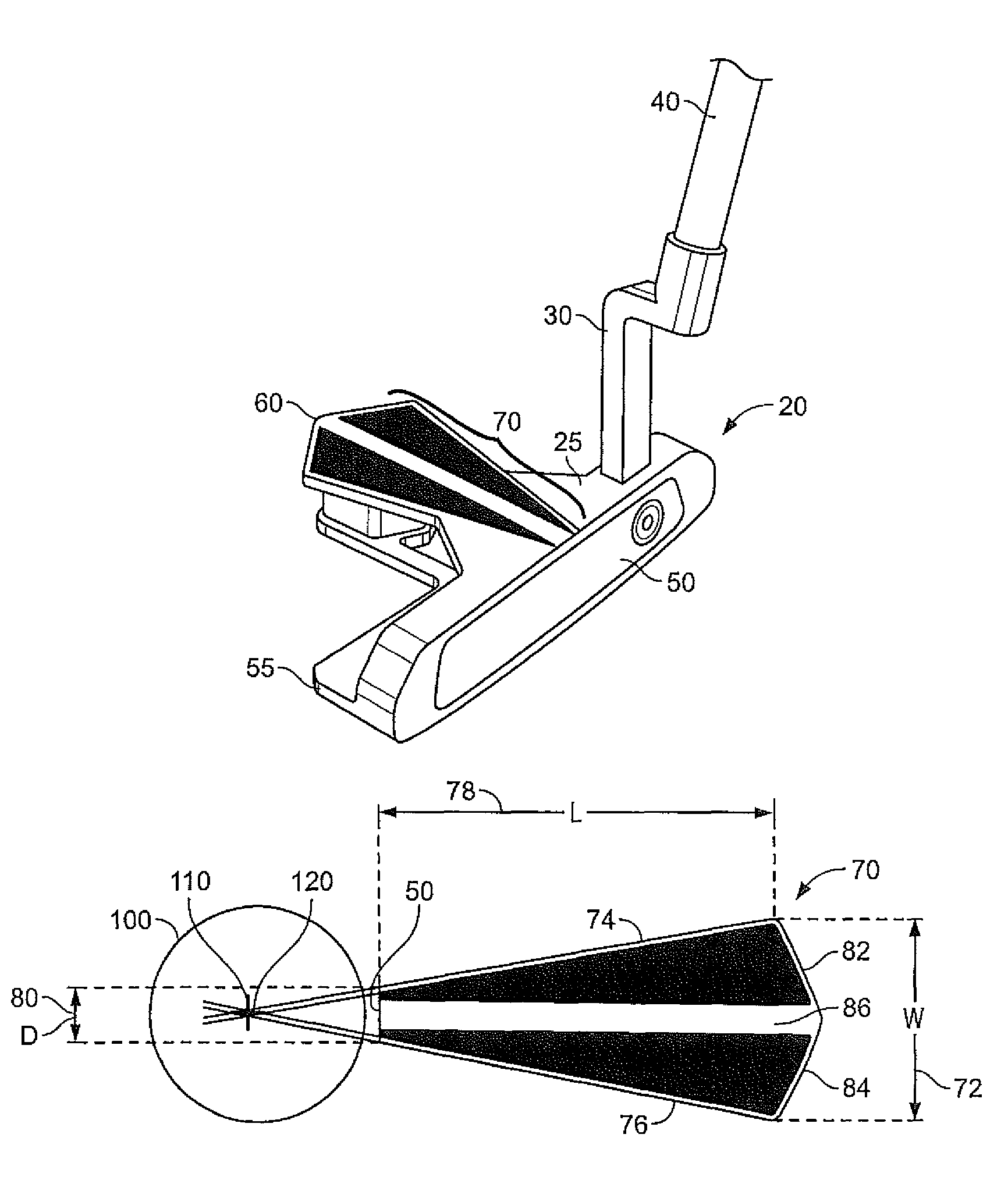
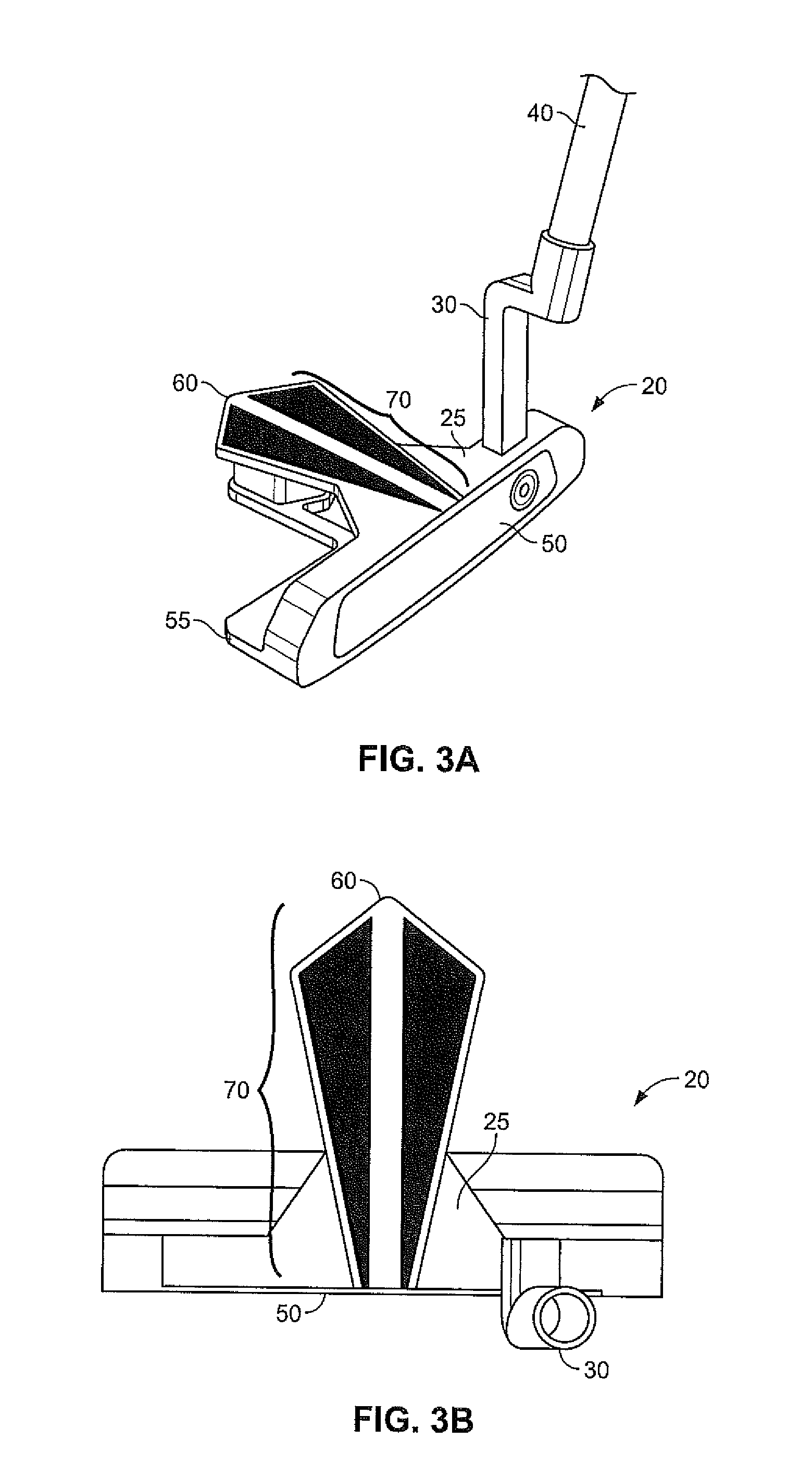
[0028]As shown in FIGS. 3A, 3B, 5A, 5B, 7A, and 7B, a putter-type club head of the present invention is generally designated 20. The club head 20 includes a top surface 25 which has an opening or hosel 30 to receive the end of a shaft 40. The club head 20 also includes a face portion 50, a sole 55, and an aft region 60. The top surface 25 of the invention includes an alignment feature 70 to help a golfer line up the putter head 20 with a golf ball 100. The putter head 20 of the present invention preferably is used with a golf ball 100 (shown in FIGS. 4A, 4B, 6A, and 6B) having a diameter of approximately 1.680 inches, but the putter head 20 may also be used with golf balls having different sizes.

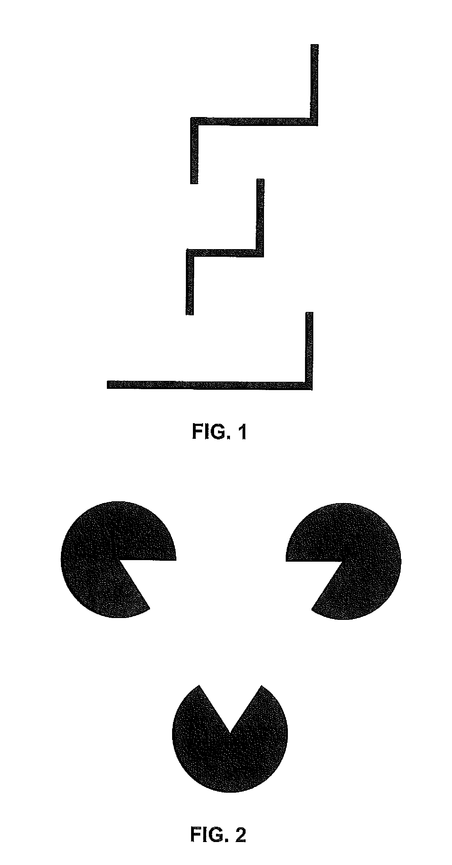
[0029]The alignment feature of the present invention 70 creates an optical illusion that assists a golfer with aligning the putter head 20 with a golf ball 100. According to Wikipedia, an optical illusion “is characterized by visually perceived images that differ from objective reality.” One...


PUM


Abstract

A golf club putter having an alignment pattern is disclosed herein. The alignment pattern has first and second long lines that approach each other as they extend from an aft region of the putter to a front region of the putter and, when the putter is properly aligned with a golf ball, create an optical illusion of convergence of said lines at or near a center of the golf ball without actually intersecting.

Description

CROSS REFERENCES TO RELATED APPLICATIONS[0001]The present application claims priority to, and is a continuation in part of, U.S. Design Pat. application No. 29 / 362,886, filed on Jun. 1, 2010, and issued as U.S. Design Pat. No. D623,710 on Sep. 14, 2010, the disclosure of which is incorporated in its entirety herein. The present application also claims priority to, and is a continuation in part of, U.S. Design Pat. application No. 29 / 367,280, filed on Aug. 5, 2010, and issued as U.S. Design Pat. No. D625,764 on Oct. 19, 2010, the disclosure of which is incorporated in its entirety herein. The present application also claims priority to, and is a continuation in part of, U.S. Design Pat. application No. 29 / 377,322, filed on Oct. 20, 2010, and issued as U.S. Design Pat. No. D641,814 on Jul. 19, 2011. The present application also claims priority to U.S. Provisional Application No. 61 / 391,938, filed on Oct. 11, 2010.STATEMENT REGARDING FEDERALLY SPONSORED RESEARCH OR DEVELOPMENT[0002]Not...

Claims


Application Information

Patent Timeline
Patent Type & Authority Patents(United States)
IPC IPC(8): A63B69/36A63B53/04
CPCA63B53/0487A63B69/3685A63B2053/0441A63B53/0441
Inventor HILTON, THOMAS R.ROLLINSTON, AUGUSTIN W.
Owner TOPGOLF CALLAWAY BRANDS CORP
Why Eureka
Try Eureka