MIMO communication system

a communication system and microphone technology, applied in the field of communication systems, can solve the problems of poor mesh node performance, large contribution of hpas to the cost of such systems, power consumption and thus eventually carbon emissions

Active Publication Date: 2013-08-20
NOKIA SOLUTIONS & NETWORKS OY
View PDF5 Cites 40 Cited by
  • Summary
  • Abstract
  • Description
  • Claims
  • Application Information

AI Technical Summary

Problems solved by technology

In particular HPAs contribute a large portion of the cost of such systems as well as the power consumption and thus eventually carbon emissions also.
However such kind of arrangement makes for poor mesh node performance when the mesh node number is increased.
RF front-end chips used in the transceivers don't usually offer high power, so high power amplifiers (HPA) are typically used.
Compared with low power PA, high power PA usually cost much and these will increase the cost of final mesh node product.
The existing HPA in the sector for the “free” radio link is wasted.
This introduces large cost and big power consumption.

Method used


Image

  • MIMO communication system
  • MIMO communication system
  • MIMO communication system

Examples


example 1

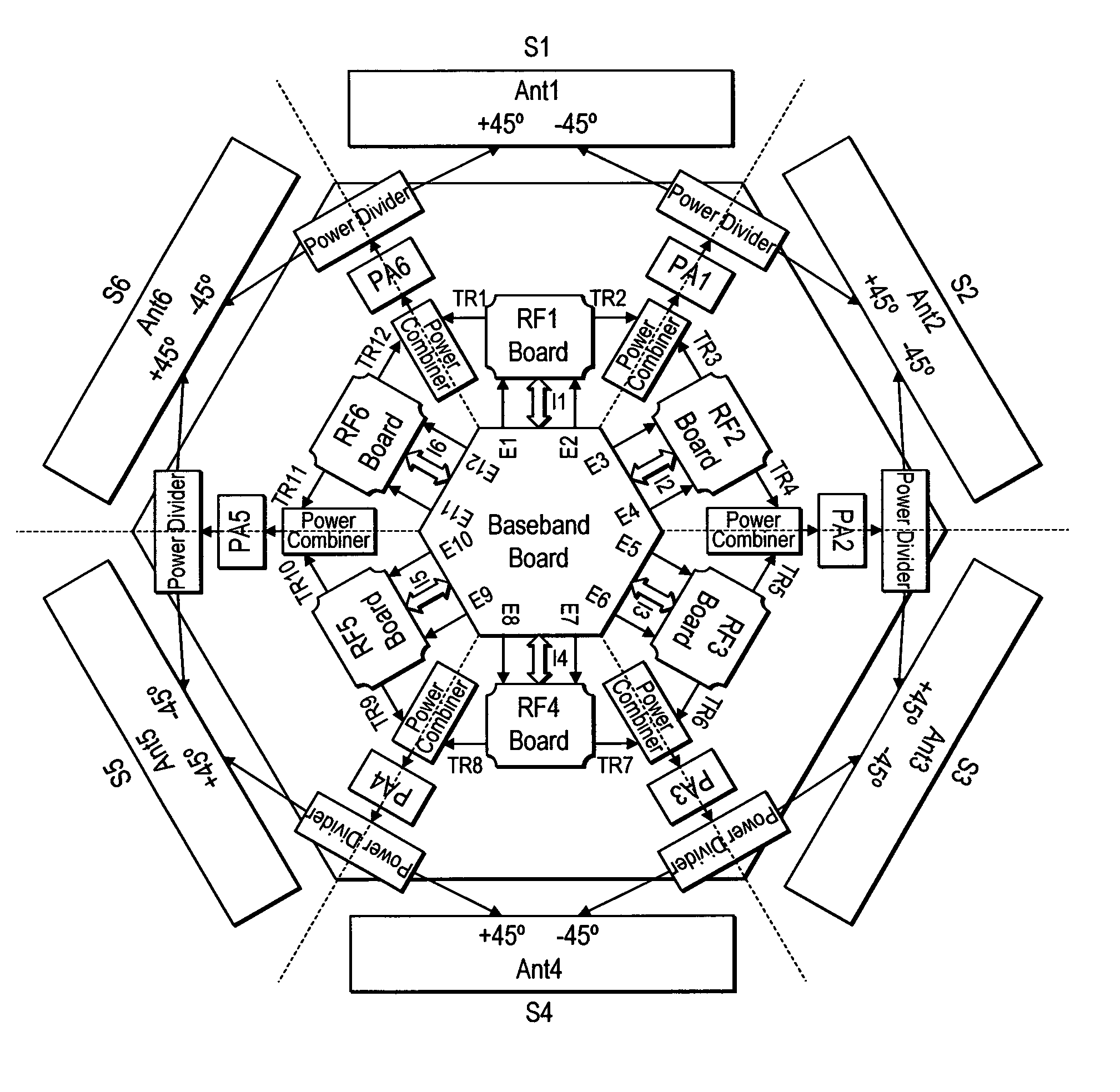
[0047]FIG. 8 illustrates in detail a particular embodiment of the invention. It shows a representation of a base station divided operably into six segments S1, S2, S3, S4, S5, S6. Each segment provides an antenna unit Ant 1 to Ant 6, each antenna unit having an antenna pair (+45°, −45°). Six power amplifiers (PA1 to PA6) are located between each segment. In this particular embodiment therefore, each PA is common (i.e. can be shared) in the operation of neighboring sectors.

[0048]Each sector includes two transceiver units (TR) located on the RF board that gives rise to transmission / reception signals (TR). The base band board part in this particular example comprises all the digital processing and protocol processing part of the mesh node or BTS. This part may be include several modules and processing units. Each board may process signal from one or multiple sectors. The baseband board may control the HPA switching between the sectors as well as provide digital baseband signal to the H...

example 2

[0056]As an alternative to SPDT switching, the switching of common HPAs between neighboring sectors may be implemented by an RF switcher matrix. This may be located between the transmitter / receiver units and the antennae.

[0057]However in certain applications where there is a relatively low power requirement, switching using SPDTs or the like is preferable due to their lower cost. RF switch matrix cost may be too high for mesh node applications.

[0058]In both the examples above, HPA's which are common to neighbouring sectors may be shared such that at different times they may be used by the neighbouring two sectors to support 2×2 MIMO (prefer to say multiple input / multiple output via two antennae.

example 3

[0059]In the above described arrangements, neighbouring sectors cannot support radio connection work at 2×2 MIMO mode at the same time i.e. simultaneously which may limit the mesh node function some times.

[0060]In a preferred embodiment of the invention therefore, the arrangement may be set up such that the functionality of the power amplifiers may be shared at the same time i.e. simultaneously. According to a preferred embodiment this may be provided by the use of a power divider. In this way MIMO signals may be provided to two neighbouring sector at the same time.

[0061]FIG. 9 shows a similar arrangement to previous figures with similar annotated components. However the SPDTs are replaced with power dividers and power combiners. There is a power combiner provided between each sector and connected between a common power amplifier PA (shared between two neighbouring sectors) and the output of two transceiver units each from different but neighbouring sectors. In addition the arrangem...


PUM


Abstract

A device and method including a plurality of transmitters and / or receiver units and antennae therefore, and wherein each of said units are arranged radially to cover a plurality of sectors; and including at least one component necessary for the operation of said units, and arranged such that said component is shared between two or more units and / or their respective antennae. The device and method has application to MIMO systems.

Description

FIELD OF THE INVENTION[0001]This invention relates to communication systems and has particular but non exclusive application to cellular communications systems as well as wireless mesh communication systems. It is applicable to transmitter / receiver elements which service other network devices such as user equipment, and whose transmitting / receiving function is divided into a number of radially distributed sectors. Further it has particular but not exclusive application to multiple input / multiple output (MIMO) systems divided into a number of sectors.BACKGROUND OF THE INVENTION[0002]A communication system is a facility which facilitates the communication between two or more entities such as communication devices, network entities and other nodes. A communication system may be provided by one or more interconnected networks. A communication device can be understood as a device provided with appropriate communication and control capabilities for enabling use thereof for communication w...

Claims


Application Information

Patent Timeline
Patent Type & Authority Patents(United States)
IPC IPC(8): H04M1/00
CPCH01Q3/24H01Q21/205H04B7/0413
Inventor SHANG, RONG RONGZHAO, ZHU YANHAMALAINEN, SEPPO OLAVIYILMAZ, OSMAN NURI CAN
Owner NOKIA SOLUTIONS & NETWORKS OY
Why Eureka
Try Eureka