
Trigger assembly

a technology of trigger assembly and trigger, which is applied in the direction of compressed gas guns, white arms/cold weapons, safety arrangements, etc., can solve the problems of user scarring and huge nois

Active Publication Date: 2013-09-03
MAN KUNG ENTERPRISE
View PDF9 Cites 52 Cited by
  • Summary
  • Abstract
  • Description
  • Claims
  • Application Information

AI Technical Summary

Benefits of technology

[0012]The present invention will become more obvious from the following description when taken in connection with the accompanying drawings which show, for purposes of illustration only, a preferred embodiment in accordance with the present invention.

Problems solved by technology

If the user unintentionally pulls the trigger A6, the arrow may touch the rear end of the pivotable member A4 and generates huge noise which may scare the user.

Method used


Image

  • Trigger assembly
  • Trigger assembly
  • Trigger assembly

Examples


Embodiment Construction

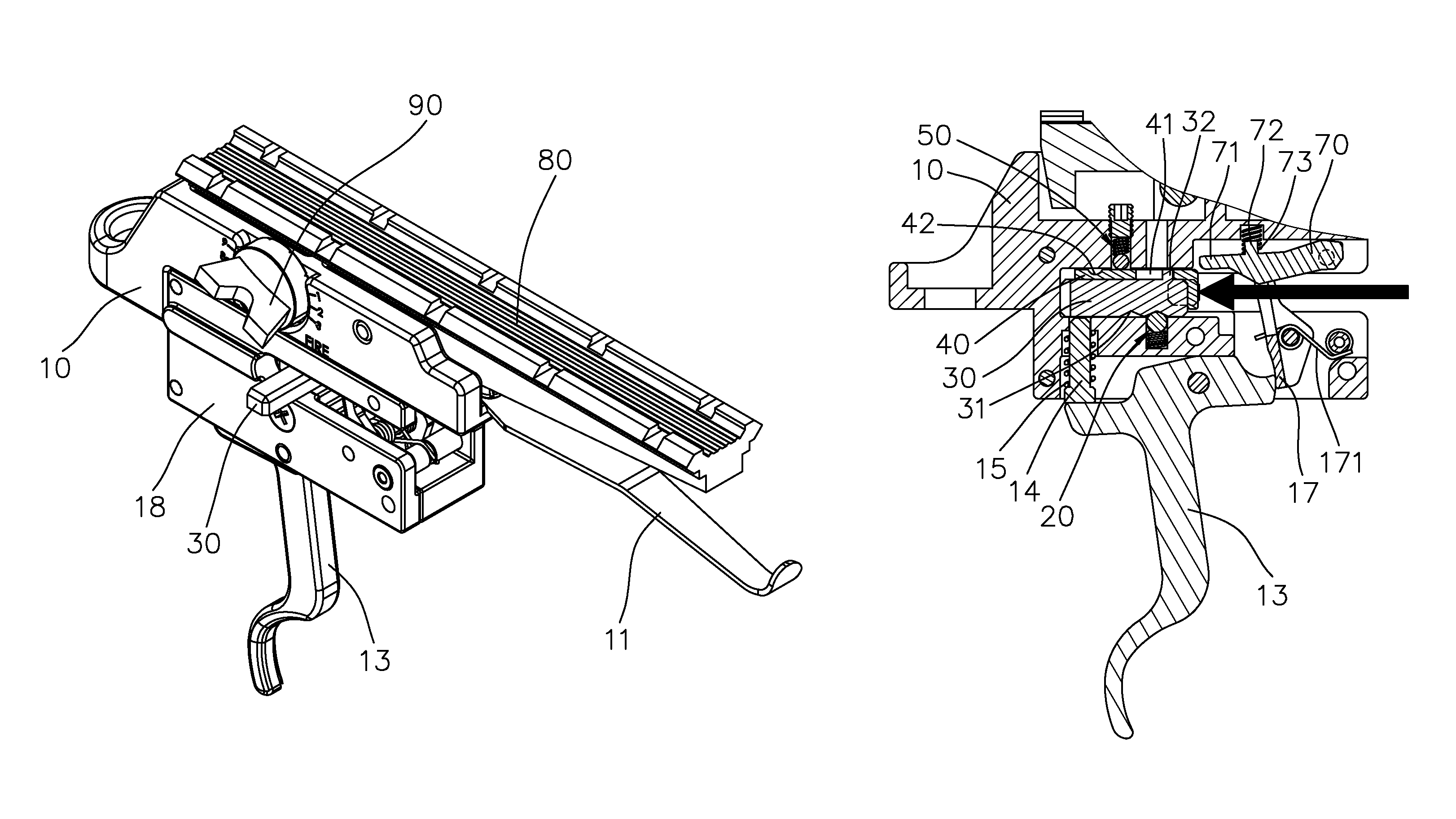
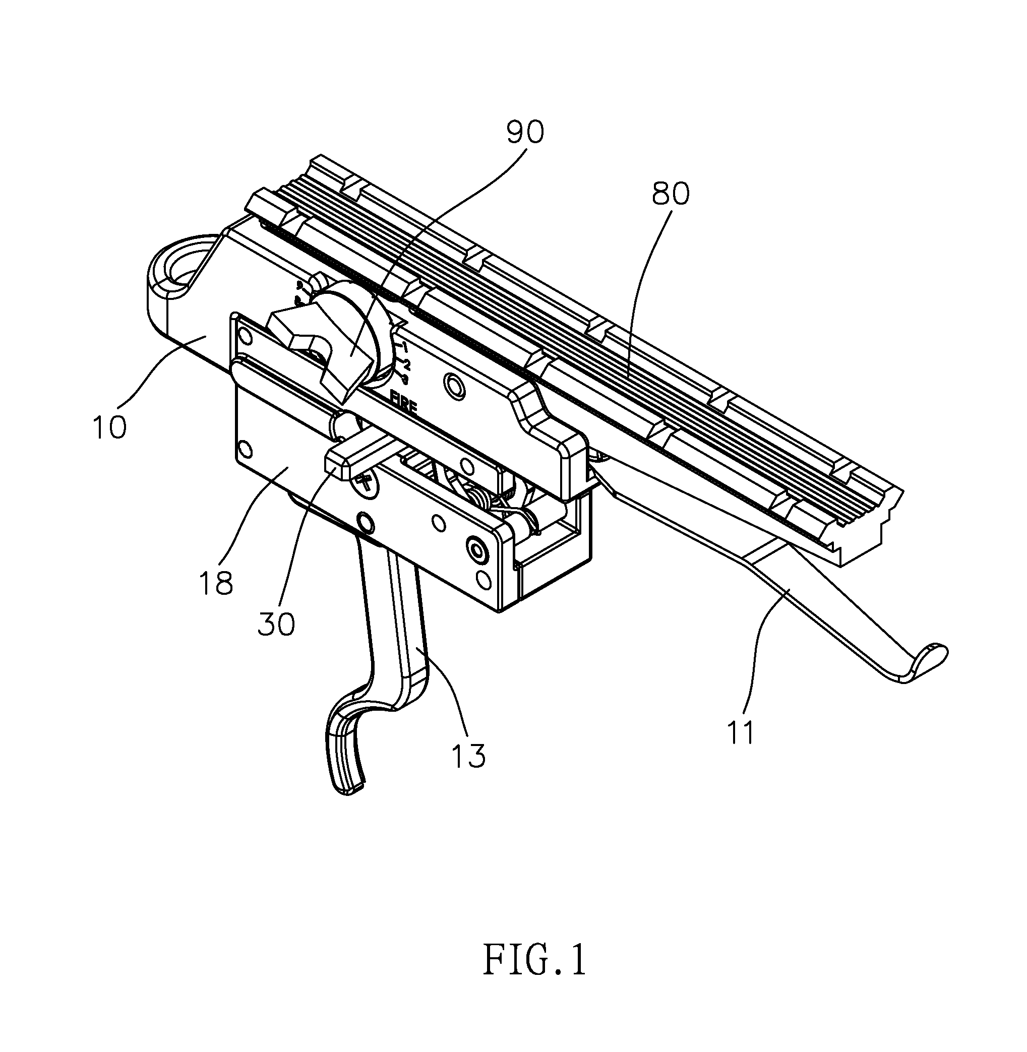
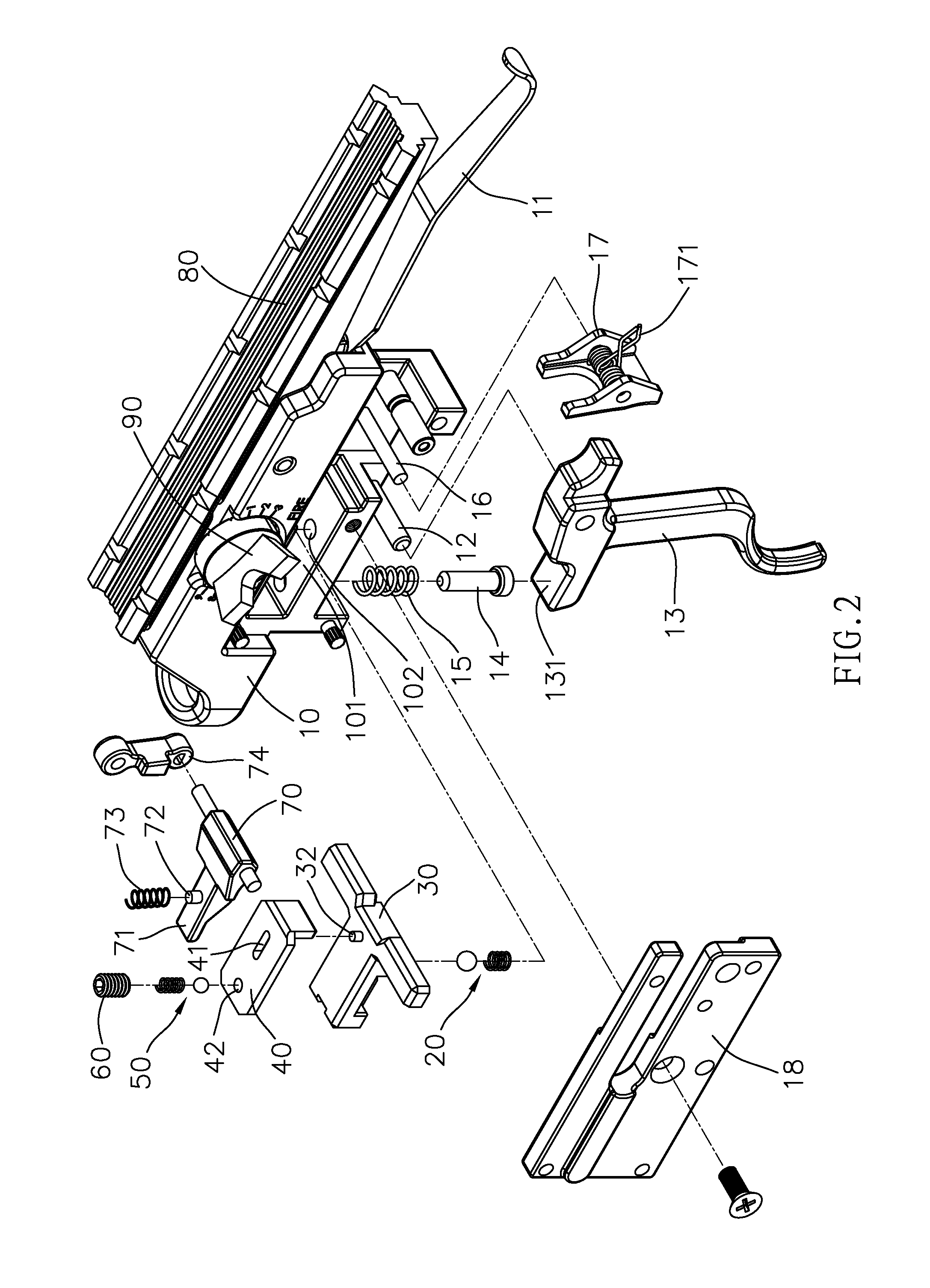
[0022]Referring to FIGS. 1 to 8, the trigger assembly or the present invention comprises a body 10 having a presser 11 and a trigger pin 12 located at the lower side of the body 10. A trigger 13 is pivotably connected to the body 10 by the trigger pin 12. and has a contact portion 131 formed on the top of one side thereof. A phi 14 contacts the contact portion 131 and a trigger spring 15 is mounted to the pin 14. A free end of the trigger spring 1 contacts the body 10 which has a pivot 16 located close to the trigger pin 12. A hook 17 is mounted to the pivot 16 and has a resilient member 171 connected thereto. A cap 18 is securely connected to one side of the body 10 so that the trigger 13 and the hook 17 do not drop from the body 10.

[0023]The body 10 has a chamber 101 and a path 102 communicates with the chamber 101. A first positioning unit 20 is located in the path 102 and a safety member 30 is located in the chamber 101. The safety member 30 has two slots 31 defined in the under...


PUM


Abstract

A trigger assembly includes a body having a pivot and a hook is mounted to the pivot. The body has a chamber and a path communicates with the chamber. A first positioning unit is located in the path and a safety member is located in the chamber which has two slots and the first positioning unit contacts the slots. An activation member is located on the top of the safety member and has a guide groove and a positioning hole. A guide rod on the safety member is located in the guide groove. A second positioning unit is located in the body and contacts the positioning hole. A pivotal member is pivotably connected to the body and has an end contacting a push portion of the activation member. A spring is mounted to the protrusion and contacts the inside of the body. The trigger assembly includes two safety protections.

Description

FIELD OF THE INVENTION[0001]The present invention relates to a trigger assembly, and more particularly, to a trigger assembly with two safety units.BACKGROUND OF THE INVENTION[0002]A conventional trigger assembly is shown in FIG. 9 and generally includes a body “A” in which an activation plate A1 is slidably inserted therein which has two positioning recesses A11 in the top thereof and each positioning recess A11 has a positioning member A2 received therein. A safety plate A3 is pivotably connected in the body “A” and a pivotable member A4 is pivotably connected in the body “A” and located close to the safety plate A3. The free end of the pivotable member A4 is connected to the body “A” by a spring A5 and a trigger A6 is connected to the lower side of the body “A”. The trigger assembly is used to shoot arrows.[0003]However, the conventional trigger assembly does not have two safety units so that when the arrow is in position, the safety plate A3 and the activation plate A1 are moved...

Claims


Application Information

Patent Timeline
Patent Type & Authority Patents(United States)
IPC IPC(8): F41B5/12
CPCF41A17/46F41A19/10
Inventor CHU, FU-HUI
Owner MAN KUNG ENTERPRISE
Features
  • Generate Ideas
  • Intellectual Property
  • Life Sciences
  • Materials
  • Tech Scout
  • Unparalleled Data Quality
  • Higher Quality Content
  • 60% Fewer Hallucinations
Learn More