Slide assembly with positioning device

a positioning device and slide technology, applied in sliding contact bearings, mechanical devices, furniture parts, etc., can solve problems such as affecting the connection of exterior equipment to the inner rail, and the movement is not smooth as expected

Active Publication Date: 2013-09-10
KING SLIDE WORKS CO LTD +1
View PDF26 Cites 19 Cited by
  • Summary
  • Abstract
  • Description
  • Claims
  • Application Information

AI Technical Summary

Problems solved by technology

However, when the rails are pulled to a distance, the portions of the rails that are not overlapped to each other cannot retain the bearings therein, so that the conventional bearing assembly has a bearing retainer to retain the bearings.
However, when the rails are pulled to the extreme expanding position, the bearing assembly is shifted by the friction of the inner rail so that it may not move to the desired position.
This makes the movement not smooth as expected.
Besides, if the bearing assembly is not moved to the desired position, the connection of exterior equipment to the inner rail is affected.

Method used


Image

  • Slide assembly with positioning device
  • Slide assembly with positioning device
  • Slide assembly with positioning device

Examples


Embodiment Construction

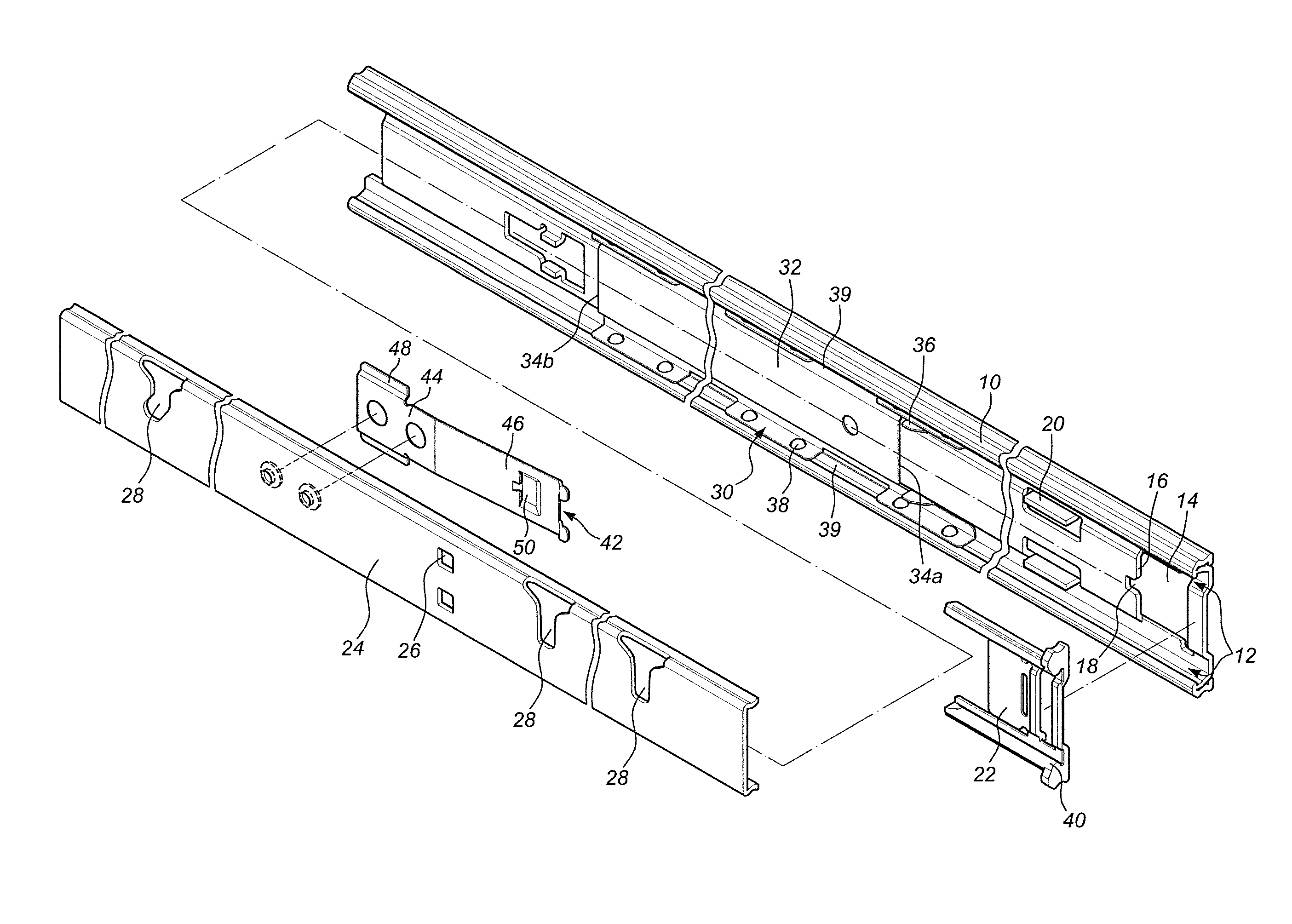
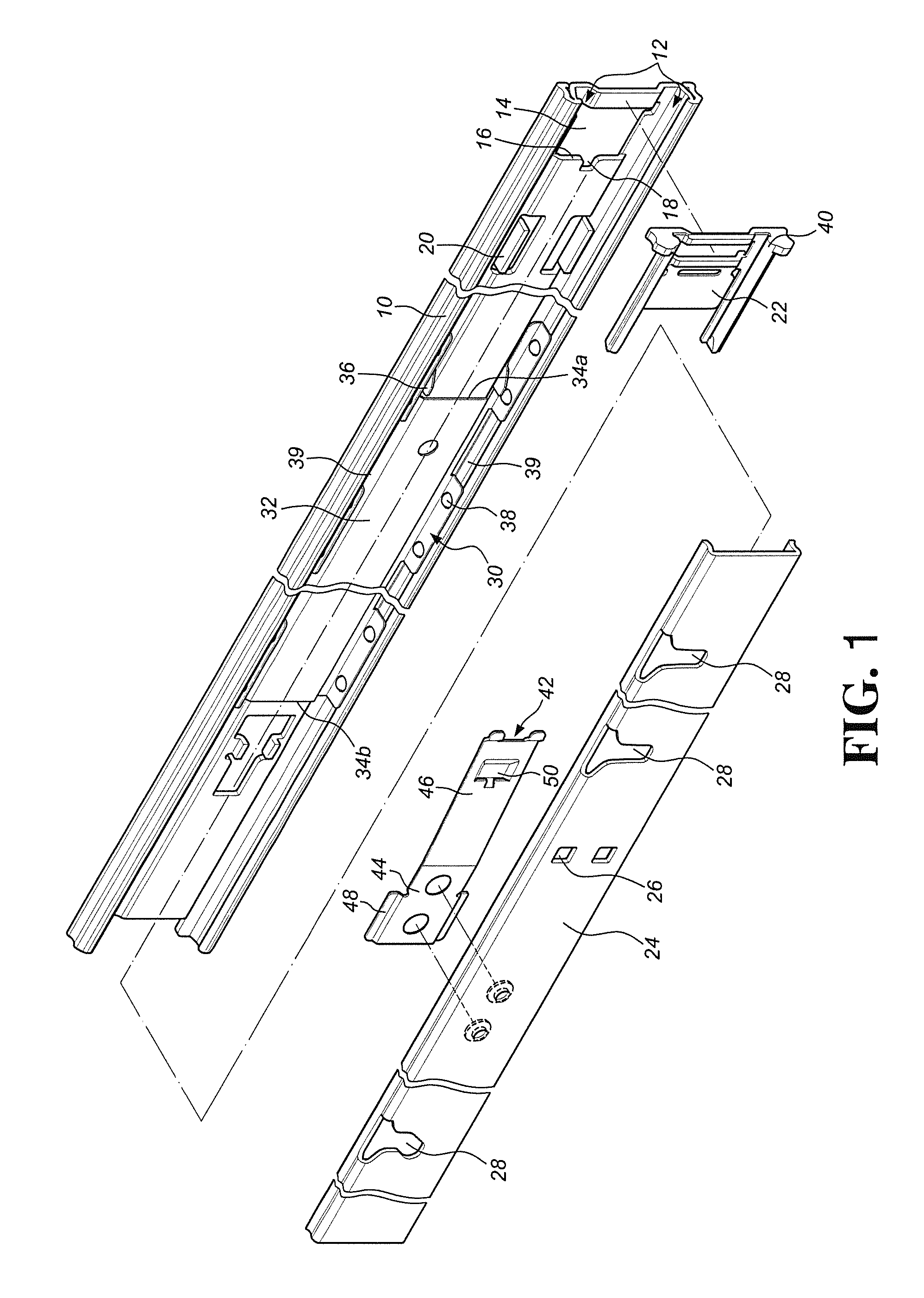
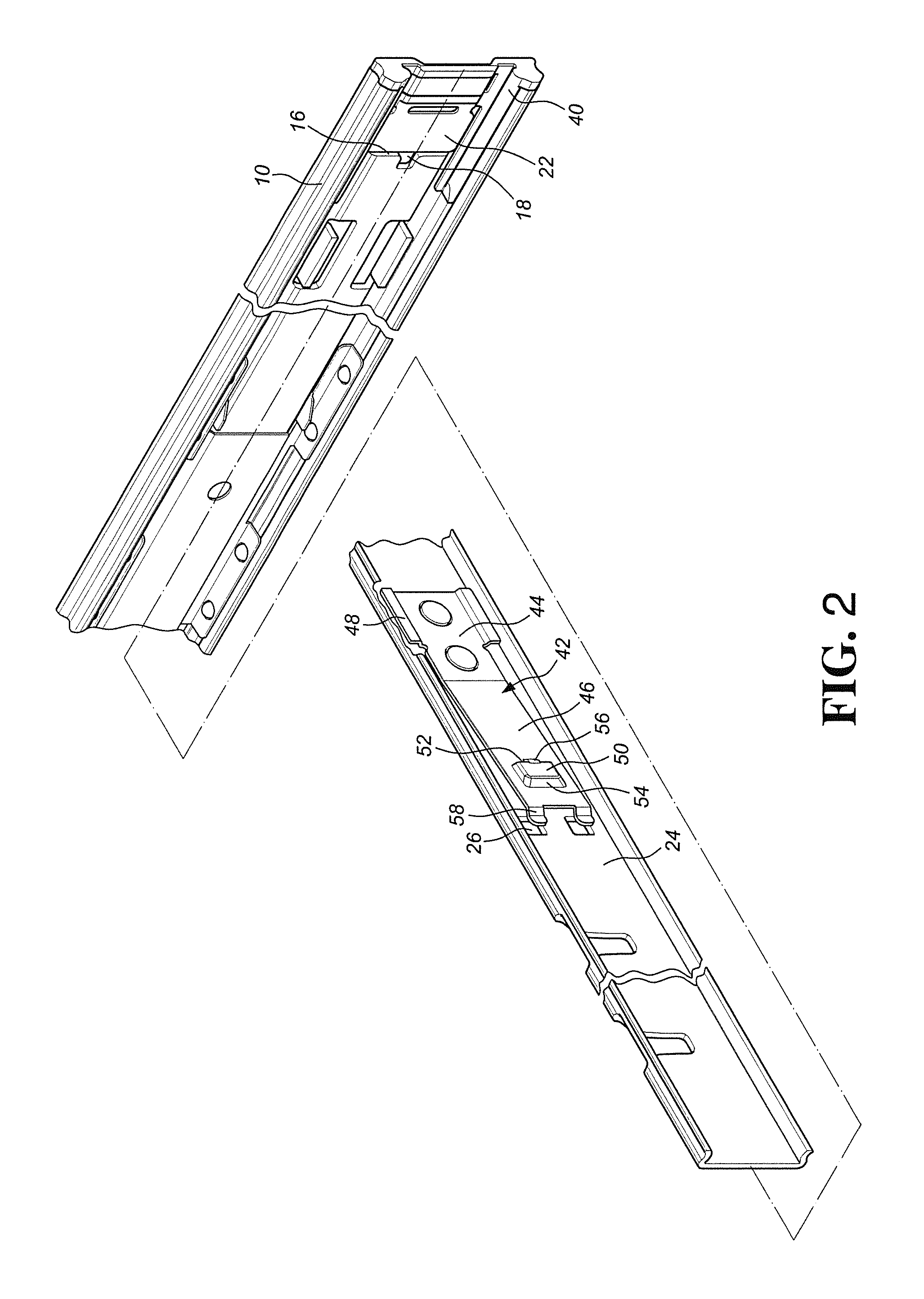
[0032]Referring to FIGS. 1 and 2, the slide assembly of the present invention comprises a first rail 10, a pressing member 22, a second rail 24, a bearing assembly 30, a stop base 40 and an engaging member 42.

[0033]The first rail 10 includes a path 12 defined along the longitudinal direction of the first rail 10 and an opening 14 is located adjacent to an end of the first rail 10. A stop face 16 is defined on a wall of the opening 14. The stop face 16 of the first rail 10 has a recess 18 which communicates with the opening 14 and a stop wall 20 is located adjacent to the opening 14.

[0034]The pressing member 22 is engaged with the opening 14 of the first rail 10.

[0035]The second rail 24 is movably located in the path 12 of the first rail 10 and may extend through the end with the opening 14. The second rail 24 has at least one through hole 26, and multiple installation holes 28 are located along the length of the second rail 24. The installation holes 28 are connected with an exterio...


PUM


Abstract

The slide assembly includes a first rail, a second rail, a bearing assembly and an engaging member. The first rail includes an opening located adjacent to an end thereof and a stop face is defined on a wall of the opening. The bearing assembly is located between the first and second rails. The bearing assembly has a bearing retainer which has a first contact portion. The engaging member is connected to the second rail and has a second contact portion and an engaging portion. The second contact portion is located corresponding to the first contact portion. When the second rail is pulled relative to the first rail, the bearing retainer is moved by engagement between the first and second contact portions. When the bearing assembly moves to a desired position, the engaging portion is inserted into the opening and contacts the stop face so that the second rail is engaged with the first rail.

Description

FIELD OF THE INVENTION[0001]The present invention relates to a slide assembly with a positioning device, and more particularly, to a bearing assembly which is moved to a pre-set position by an engaging member when the second rail is pulled out relative to the first rail, and the second rail is engaged with the first rail.BACKGROUND OF THE INVENTION[0002]The conventional rails are used to the drawers of furniture or the chassis on the computer rack so as to support the slide of the drawer or the chassis. Generally, the bearing assembly includes a plurality of bearings which allow the rails to be easily pulled relative to another. However, when the rails are pulled to a distance, the portions of the rails that are not overlapped to each other cannot retain the bearings therein, so that the conventional bearing assembly has a bearing retainer to retain the bearings. The bearing retainer separates the bearings so that the bearings are not in contact with each other.[0003]The bearing ass...

Claims


Application Information

Patent Timeline
Patent Type & Authority Patents(United States)
IPC IPC(8): A47B88/00A47B95/00
CPCA47B88/14A47B88/16F16C29/005F16C29/046F16C29/048A47B2088/0444A47B2210/0018A47B2210/0035A47B2210/0059A47B88/487A47B88/57A47B2088/4235H05K7/1489
Inventor CHEN, KEN-CHINGHUANG, CHIEN-LIWANG, CHUN-CHIANG
Owner KING SLIDE WORKS CO LTD
Why Eureka
Try Eureka