Beam forming method and multiple antenna system using the same

a beam forming and antenna technology, applied in the field of beam forming methods and multiple antenna systems using the same, can solve the problem of excessive time consumption, and achieve the effect of reducing the transmission frequency

Active Publication Date: 2013-11-12
SAMSUNG ELECTRO MECHANICS CO LTD +1
View PDF5 Cites 35 Cited by
  • Summary
  • Abstract
  • Description
  • Claims
  • Application Information

AI Technical Summary

Benefits of technology

[0008]An aspect of the present invention provides a beam forming method capable of reducing a transmission frequency of a training sequence and a multiple antenna system using the same.
[0009]According to an exemplary embodiment of the present invention, there is provided a multiple antenna system forming optimal beam patterns through a transmission of a training sequence between a transmitter and a receiver each including a plurality of antennas, the multiple antenna system including: a transmitter selecting predetermined antennas to be activated according to a stepwise increased level for forming the optimal beam patterns, and transmitting the training sequence to a receiver through the selected antennas; and a receiver selecting the predetermined antennas to be activated according to the level and transmitting to the transmitter an index of an optimal transmission weight vector significantly reducing a cost function based on the training sequence transmitted from the transmitter, wherein the transmitter selects antennas so that the beam patterns formed by the antennas selected at a q-th level (q: the index of the level) include the beam patterns formed by the antennas selected at a q+1-th level.
[0015]According to an exemplary embodiment of the present invention, there is provided a beam forming method of forming optimal beam patterns through a transmission of a training sequence between a transmitter and a receiver each including a plurality of antennas, the beam forming method including: (a) selecting predetermined antennas of a transmitter and a receiver to be activated according to a stepwise increased level for forming the optimal beam patterns; (b) transmitting the training sequence from the transmitter to the receiver through the selected antennas; and (c) transmitting an index of an optimal transmission weight vector significantly reducing a cost function based on the training sequence received in the receiver to the transmitter, wherein the operation (a) includes selecting antennas so that the beam patterns formed by the antennas selected at a q-th level (q: the index of the level) include the beam patterns formed by the antennas selected at a q+1-th level.

Problems solved by technology

However, in performing the transmission procedure of the training sequence, the transmission frequency of the training sequence is increased and thus, an excessive amount of time is consumed.

Method used


Image

  • Beam forming method and multiple antenna system using the same
  • Beam forming method and multiple antenna system using the same
  • Beam forming method and multiple antenna system using the same

Examples


Embodiment Construction

[0027]Exemplary embodiments of the present invention will now be described in detail with reference to the accompanying drawings. However, it should be noted that the spirit of the present invention is not limited to the embodiments set forth herein and those skilled in the art and understanding the present invention can easily accomplish retrogressive inventions or other embodiments included in the spirit of the present invention by the addition, modification, and removal of components within the same spirit, but those are construed as being included in the spirit of the present invention.

[0028]Further, throughout the drawings, the same or like reference numerals will be used to designate components having the same functions in the scope of the similar idea.

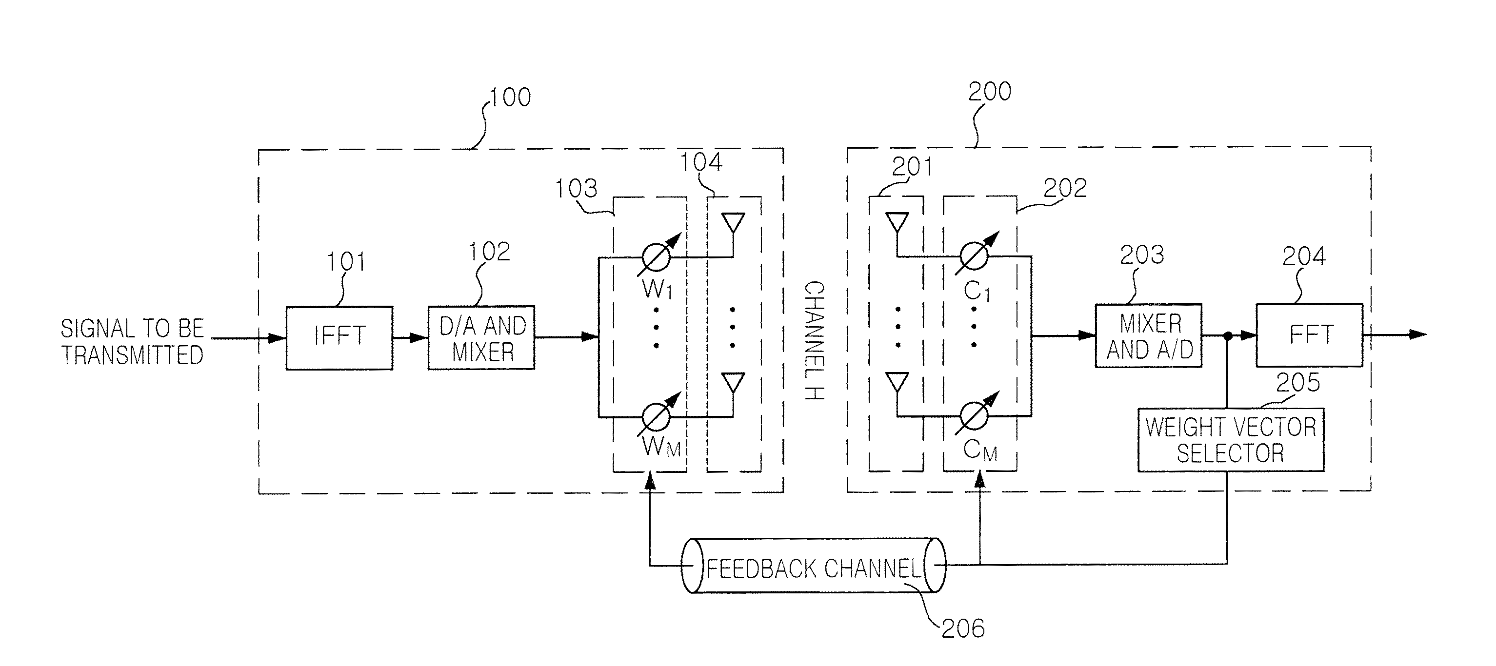
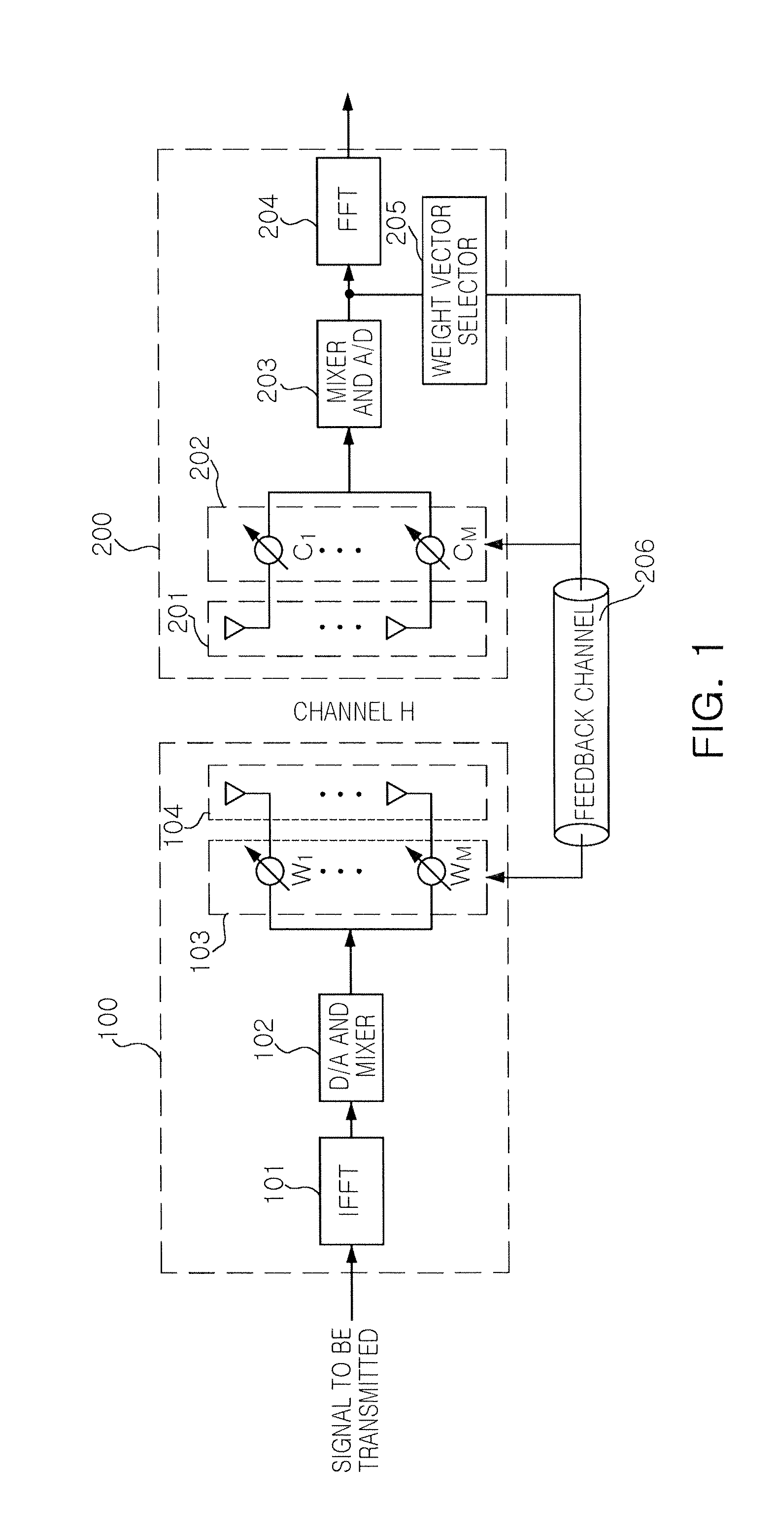
[0029]FIG. 1 is a configuration diagram of a multiple antenna system according to an exemplary embodiment of the present invention. The multiple antenna system may include a transmitter 100 and a receiver 200.

[0030]In detail, an...


PUM


Abstract

Disclosed are a beam forming method and a multiple antenna system using the same. There is provided a multiple antenna system which forms optimal beam patterns through a transmission of a training sequence between a transmitter and a receiver, each including a plurality of antennas, the multiple antenna system comprising: a transmitter selecting antennas to be activated according to a level and transmitting the training sequence to a receiver through the selected antennas; a receiver selecting the antennas to be activated according to the level and transmitting to the transmitter an index of an optimal transmission weight vector significantly reducing a cost function based on the training sequence transmitted from the transmitter, wherein the transmitter selects antennas so that the beam patterns formed by the antennas selected at a q-th level (q: the index of the level) include the beam patterns formed by the antennas selected at a q+1-th level. As a result, the transmission frequency of the training sequence may be reduced.

Description

CROSS-REFERENCE TO RELATED APPLICATIONS[0001]This application claims the priority of Korean Patent Application No. 10-2011-0011050 filed on Feb. 8, 2011, in the Korean Intellectual Property Office, the disclosure of which is incorporated herein by reference.BACKGROUND OF THE INVENTION[0002]1. Field of the Invention[0003]The present invention relates to a beam forming method capable of reducing a transmission frequency of a training sequence and a multiple antenna system using the same.[0004]2. Description of the Related Art[0005]Recently, schemes to solve a lack of telecommunications frequency resources have been sought. One of these schemes, millimeter wave band communication, is drawing great attention due to the merits of using broadband to obtain a high transmission rate. In addition, since the miniaturization and lightness of an RF device may be implemented due to a short wavelength, international standardization standards for wireless local area networks (WLAN) and a wireless ...

Claims


Application Information

Patent Timeline
Patent Type & Authority Patents(United States)
IPC IPC(8): H04B1/00H04B7/00
CPCH04B7/0617H04B7/0634H04B7/0639H04L5/0023H04L5/0048H01Q21/06
Inventor PARK, JOUN SUPPARK, CHUL GYUNKO, YOUNG CHAILEE, HYUN HO
Owner SAMSUNG ELECTRO MECHANICS CO LTD
Why Eureka
Try Eureka