Replacement necessity determination device for snap-in valve

a technology of necessity determination and snap-in valve, which is applied in the direction of fluid tightness measurement, instruments, vehicle sub-unit features, etc., can solve the problems of secular degradation, acceleration sensor cannot appropriately detect the acceleration of the wheel assembly in the radial direction, and the tire air pressure quickly decreases

Inactive Publication Date: 2019-07-16
TOYOTA JIDOSHA KK
View PDF6 Cites 3 Cited by
  • Summary
  • Abstract
  • Description
  • Claims
  • Application Information

AI Technical Summary

Benefits of technology

[0013]It is a primary object of exemplary aspects of the present disclosure to provide a device capable of predicting a secular degradation of an elastic body of a snap-in valve to which an air pressure detection device is integrally coupled based on stress applied to the elastic body, thereby determining necessity of replacement of the snap-in valve.
[0033]According to the above-mentioned aspect, the rotational speeds of the wheel are calculated based on the increase / decrease cycle of the acceleration. Thus, the acceleration detected by the acceleration sensor provided for the air pressure detection device can effectively be used to acquire the rotational speeds of the wheel. Thus, a special wheel assembly speed detection device, e.g., a wheel assembly speed sensor, is not necessary, and hence the replacement necessity determination device can also be applied to a vehicle in which the wheel assembly speed sensor is not provided for each of the wheel assemblies.
[0035]According to the above-mentioned aspect, the information on the rotational speed is acquired from the wheel assembly speed sensor as the information on the rotational speed of the wheel. Thus, the rotational speed of the wheel can be calculated without necessity for the information on the acceleration detected by the acceleration sensor. The information on the acceleration detected by the acceleration sensor is wirelessly transmitted by the transmitter to the control device, and hence compared with the case where the rotational speed of the wheel is calculated based on the increase / decrease cycle of the acceleration, a transmission frequency of the information on the acceleration by the transmitter can be decreased, thereby decreasing an electrical energy amount consumed by the transmitter.

Problems solved by technology

When the mounting of the valve to the rim portion is defective, the air at a high pressure inside the tire leaks via a gap between the valve and the rim portion, resulting in a fast decrease in the tire air pressure.
Thus, when the mounting of the valve to the rim portion is defective, the valve unit is pivoted by a centrifugal force caused by the rotation of the wheel assembly, and the acceleration sensor cannot appropriately detect the acceleration of the wheel assembly in the radial direction thereof.
When the valve of the valve unit is the snap-in valve, and the valve unit pivots as a result of a centrifugal force caused by the rotation of the wheel assembly, the elastic body is deformed, resulting in a secular degradation.
Thus, the ratio of the second acceleration to the first acceleration cannot be used as an indication of the secular degradation of the elastic body, and hence the abnormality detection device described in Japanese Patent Application Laid-open No. 2005-170224 cannot be used to determine whether or not the replacement of the snap-in valve caused by the secular degradation of the elastic body is necessary.

Method used


Image

  • Replacement necessity determination device for snap-in valve
  • Replacement necessity determination device for snap-in valve
  • Replacement necessity determination device for snap-in valve

Examples


first embodiment

[0045][First Embodiment]

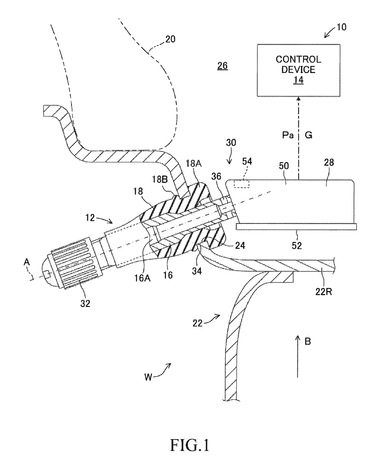
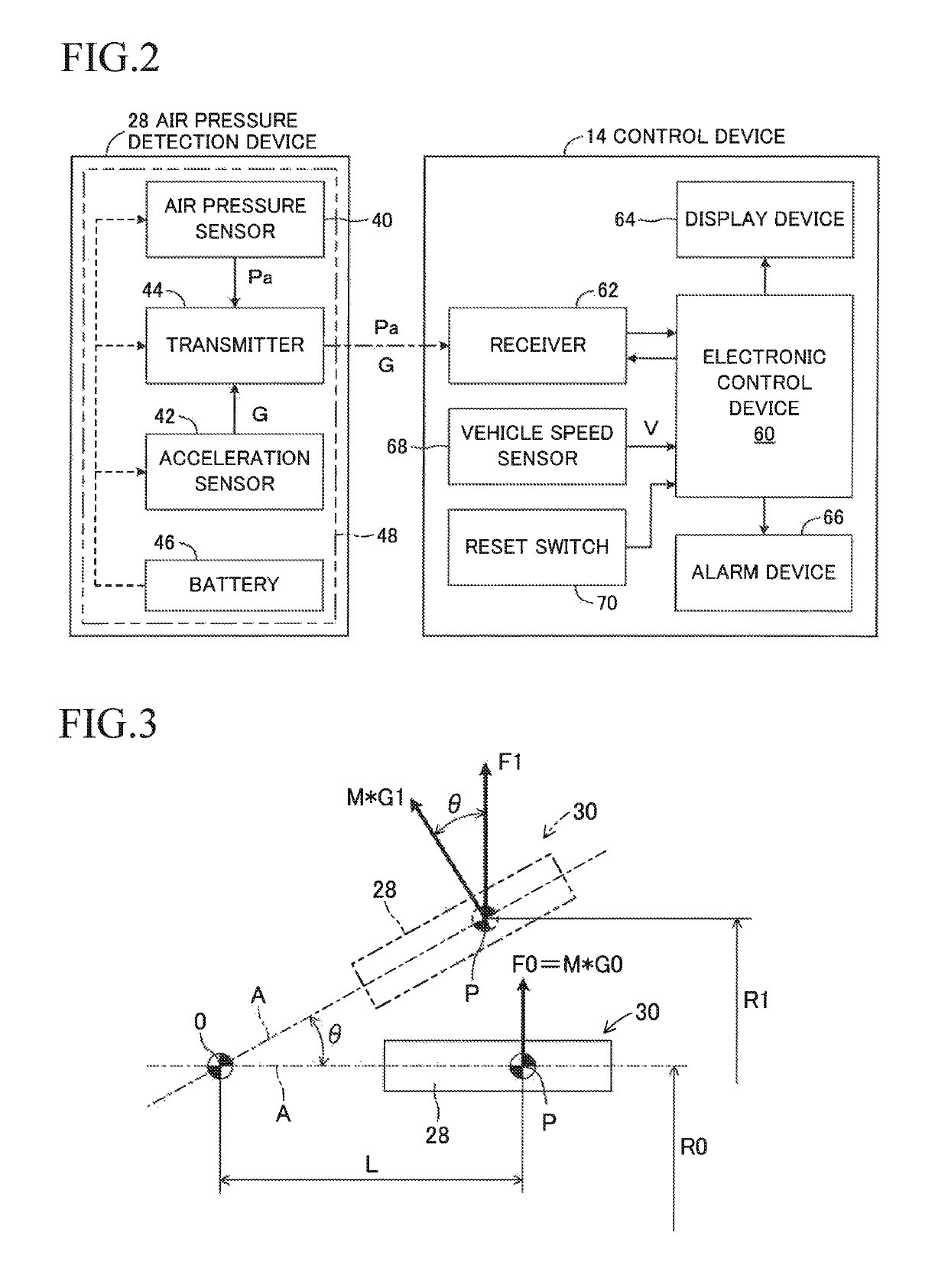
[0046]A replacement necessity determination device 10 illustrated in FIG. 1, which is a schematic configuration diagram, and FIG. 2, which is a block diagram, includes a control device 14 for determining replacement necessity for a snap-in valve 12. The snap-in valve 12 includes a valve stem 16 having a tubular shape extending along an axis A, and an elastic body 18 covering an entire periphery of a region except for both ends of the valve stem 16. The valve stem 16 is formed of metal. The elastic body 18 is formed of rubber. The valve stem 16 may be formed of rigid plastic, and the elastic body 18 may be formed of resin. In each wheel assembly W of a vehicle (not shown), one snap-in valve 12 is installed on a metal wheel 22 for retaining a tire 20 on an outer periphery thereof, but the control device 14 is installed in a vehicle body of the vehicle as one control device common to the plurality of snap-in valves 12.

[0047]As illustrated in FIG. 1, the snap-in ...

second embodiment

[0112][Second Embodiment]

[0113]FIG. 5 is a block diagram of the replacement necessity determination device 10 according to a second embodiment of the present disclosure. In FIG. 5, the same components as the components illustrated in FIG. 2 are denoted by the same reference symbols as those assigned in FIG. 2.

[0114]According to the second embodiment, wheel assembly speeds Vwi [rpm] (i=fl, fr, rl, and rr) of the front left, front right, rear left, and rear right wheel assemblies (not shown) are detected by wheel assembly speed sensors 72i (i=fl, fr, rl, and rr). Signals representing the wheel assembly speeds Vwi are input to the electronic control device 60 from the wheel assembly speed sensors 72i.

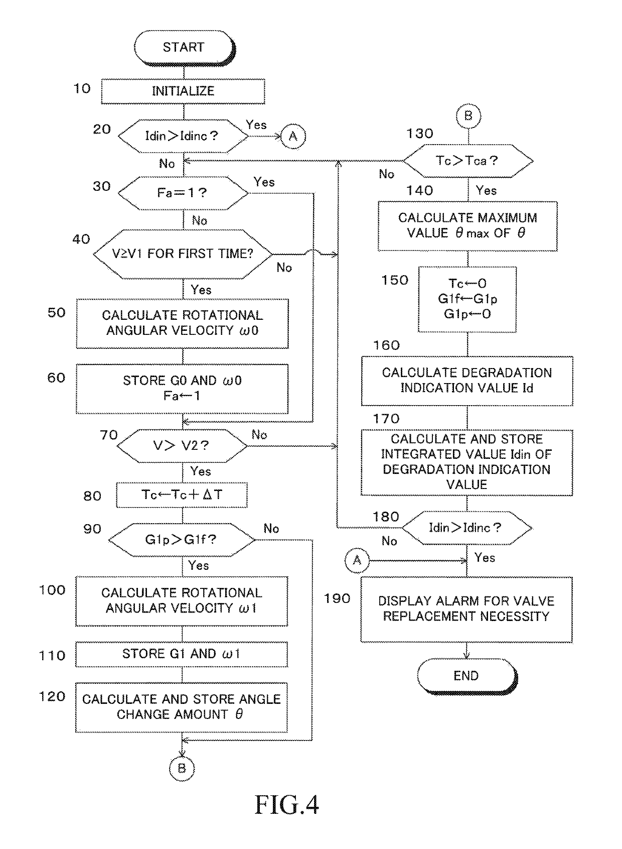
[0115]Further, according to the second embodiment, the determination control for the necessity of the replacement of the snap-in valve 12 is carried out in accordance with a flowchart illustrated in FIG. 6. In FIG. 6, the same step as the step illustrated in FIG. 4 is denoted by the same ...

third embodiment

[0123][Third Embodiment]

[0124]FIG. 7 is a flowchart for illustrating a principal part of a determination control routine for replacement necessity for the snap-in valve 12 in the replacement necessity determination device 10 according to a third embodiment of the present disclosure constructed as a modified example of the first and second embodiments.

[0125]According to the third embodiment, Step 10 to Step 170 are carried out in the same manner as in the cases of the first and second embodiments, but Step 175 is carried out in place of Step 180 when Step 170 is completed.

[0126]In Step 175, it is determined whether or not the integrated value Idin of the degradation indication value Id is more than a first reference value Idinc1 set in advance, that is, it is determined whether or not the timing of the replacement of the snap-in valve 12 is approaching. When a negative determination is made, the control returns to Step 30, and when an affirmative determination is made, the control pr...


PUM


Abstract

Provided is a replacement necessity determination device for a snap-in valve having an inner end to which an air pressure detection device including an air pressure sensor and an acceleration sensor is coupled. A control device of the replacement necessity determination device is configured to predict an angle change amount of the snap-in valve and the air pressure detection device with respect to a wheel caused by a centrifugal force based on a rotational speed of the wheel and an acceleration detected by the acceleration sensor, calculate a degradation indication value of an elastic body of the snap-in valve based on a maximum value of the angle change amount during a period set in advance, and determine necessity of replacement of the snap-in valve based on an integrated value of the degradation indication value.

Description

CROSS-REFERENCE TO RELATED APPLICATION[0001]The disclosures of Japanese Patent Application No. JP 2016-33128 filed on Feb. 24, 2016 is incorporated herein by reference in its entirety.BACKGROUND[0002]1. Technical Field[0003]The present disclosure relates to a replacement necessity determination device for a snap-in valve to which an air pressure detection device is integrally coupled.[0004]2. Description of the Related Art[0005]There is known a valve unit, which is used for a wheel assembly of a vehicle, e.g., a motor vehicle, and has a function of detecting an air pressure. The valve unit includes a valve for adjusting a tire air pressure, and an air pressure detection device integrally coupled to one end of the valve. The air pressure detection device includes an air pressure detection sensor and an acceleration sensor for detecting the rotation of the wheel assembly, and the acceleration sensor is configured to detect an acceleration of the wheel assembly in a radial direction th...

Claims


Application Information

Patent Timeline
Patent Type & Authority Patents(United States)
IPC IPC(8): F16K15/20B60C29/02B60C23/04F16K37/00B60C19/00G01M3/28
CPCF16K37/0091B60C23/0408B60C23/0481B60C23/0488B60C23/0494B60C29/02G01M3/2876F16K15/20B60Y2400/3032B60C2019/004B60C2019/007B60Y2400/301B60Y2400/304B60C23/04B60C29/00G01D21/02
Inventor TAKI, YUJI
Owner TOYOTA JIDOSHA KK
Why Eureka
Try Eureka