Staple position sensor system

a sensor system and staple technology, applied in the field of surgical staples, can solve the problems of insufficient hemostasis and adverse consequences

Inactive Publication Date: 2013-12-03
COVIDIEN LP
View PDF16 Cites 1186 Cited by
  • Summary
  • Abstract
  • Description
  • Claims
  • Application Information

AI Technical Summary

Problems solved by technology

Improperly formed staples can cause adverse consequences, such as, for example, inadequate hemostasis.

Method used


Image

  • Staple position sensor system
  • Staple position sensor system
  • Staple position sensor system

Examples


Embodiment Construction

[0030]Various embodiments of the presently disclosed surgical stapling apparatus will now be described in detail with reference to the drawings, wherein like reference numerals identify similar or identical elements. In the drawings and in the description that follows, the term “proximal,” will refer to the end of a device or system that is closest to the operator, while the term “distal” will refer to the end of the device or system that is farthest from the operator.

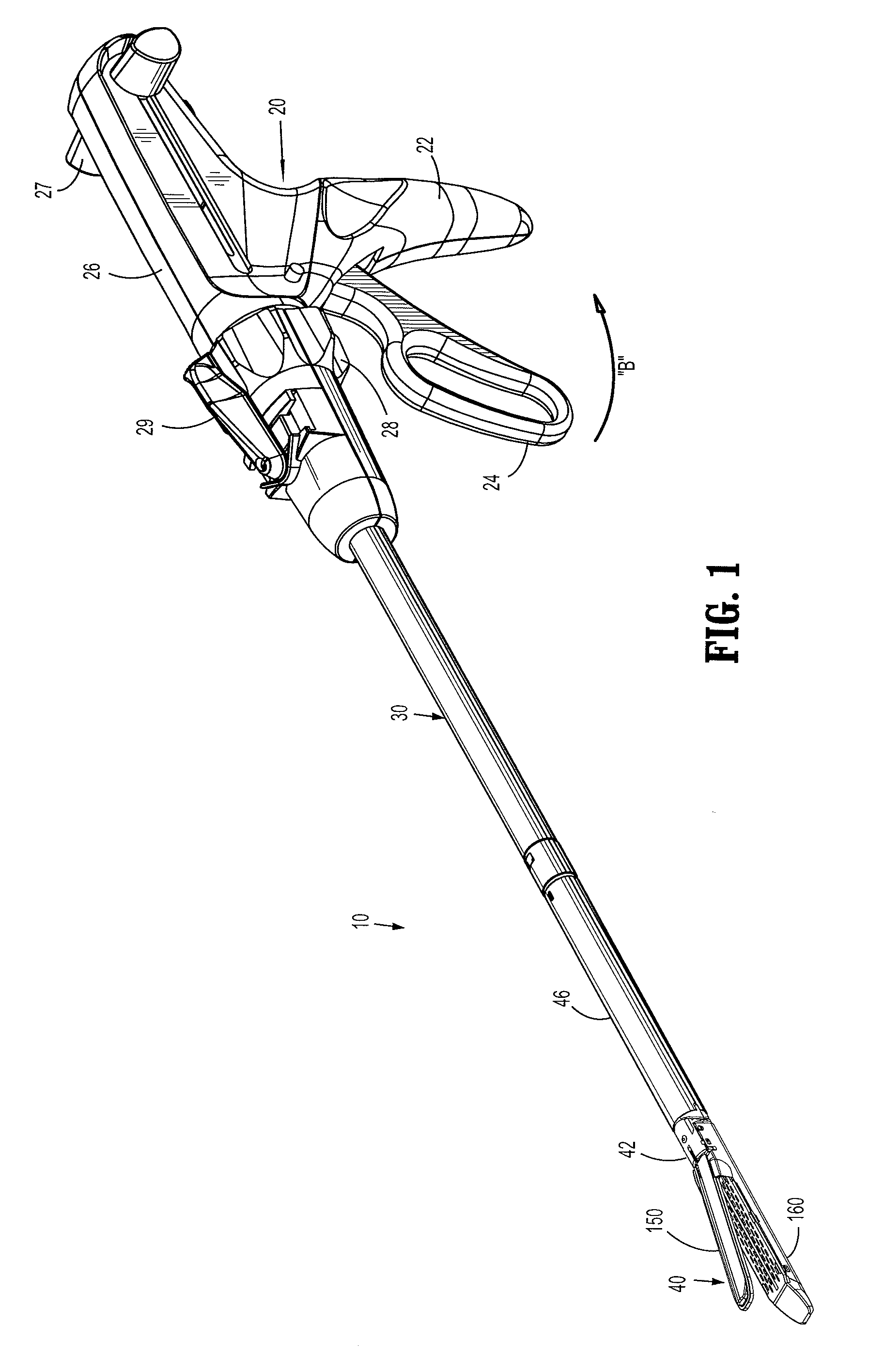
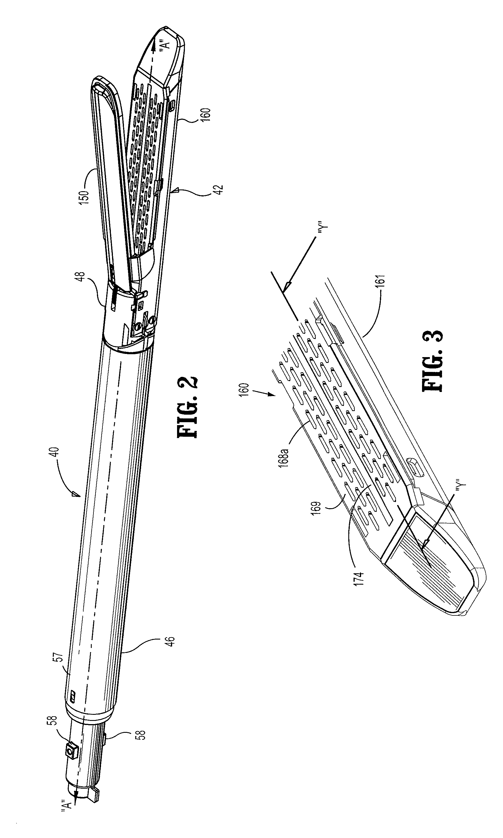
[0031]A surgical stapling apparatus is illustrated in FIG. 1 and is designated by the reference numeral 10. Surgical stapling apparatus 10 includes a handle assembly 20, an elongate body 30 extending distally from handle assembly 20 and a disposable loading unit 40 releasably secured to a distal end of elongate body 30. Disposable loading unit 40 includes a tool assembly 42 having a cartridge assembly 160 and an anvil assembly 150 movably secured in relation to cartridge assembly 160. Disposable loading unit 40 is conf...


PUM

PropertyMeasurementUnit
timeaaaaaaaaaa
rotationaaaaaaaaaa
anglesaaaaaaaaaa

Abstract

A surgical stapling instrument includes a handle assembly, an elongate shaft extending distally from the handle assembly, and a tool assembly coupled to a distal end of the elongate shaft. The tool assembly includes a cartridge assembly including a plurality of surgical staples each including a code embedded portion and a first sensor for detecting the position of the surgical staples prior to and during a formation of the staples. The tool assembly further includes an anvil assembly including a second sensor that detects the position of the surgical staples after the formation of the surgical staples.

Description

CROSS REFERENCE TO RELATED APPLICATION[0001]The present application claims the benefit of and priority to U.S. Provisional Application Ser. No. 61 / 356,195 filed on Jun. 18, 2010, the entire contents of which are incorporated herein by reference.BACKGROUND[0002]1. Technical Field[0003]The present disclosure relates to a surgical stapling instrument and, more particularly, to a staple position sensor system.[0004]2. Background of Related Art[0005]Surgical stapling instruments used for sequentially applying linear rows of surgical staples through tissue are well known in the art. Surgical staplers of this type may be used during an open surgical procedure where an incision is made to provide access to the surgical site or during an endoscopic or laparoscopic surgical procedure where stapling is accomplished through a generally cylindrical access tube. Endoscopic and laparoscopic surgical instruments are often preferred over traditional open surgical devices since a smaller incision ten...

Claims


Application Information

Patent Timeline
Patent Type & Authority Patents(United States)
IPC IPC(8): A61B17/068
CPCA61B17/07207A61B17/0682A61B17/0644A61B2017/00482A61B2017/07271A61B2019/4857A61B2017/07257A61B2090/0811A61B17/068
Inventor OKONIEWSKI, GREGORY
Owner COVIDIEN LP
Why Eureka
Try Eureka