Rifling angle calculating method

a calculating method and angle technology, applied in the direction of weapons, launching weapons, instruments, etc., can solve the problems of inability to meet boundary conditions, the life of the gun barrel or the flight of the projectile may be negatively affected, etc., and achieve the effect of minimizing the maximum value of rifling for

Inactive Publication Date: 2014-01-28
AGENCY FOR DEFENSE DEV
View PDF6 Cites 4 Cited by
  • Summary
  • Abstract
  • Description
  • Claims
  • Application Information

AI Technical Summary

Benefits of technology

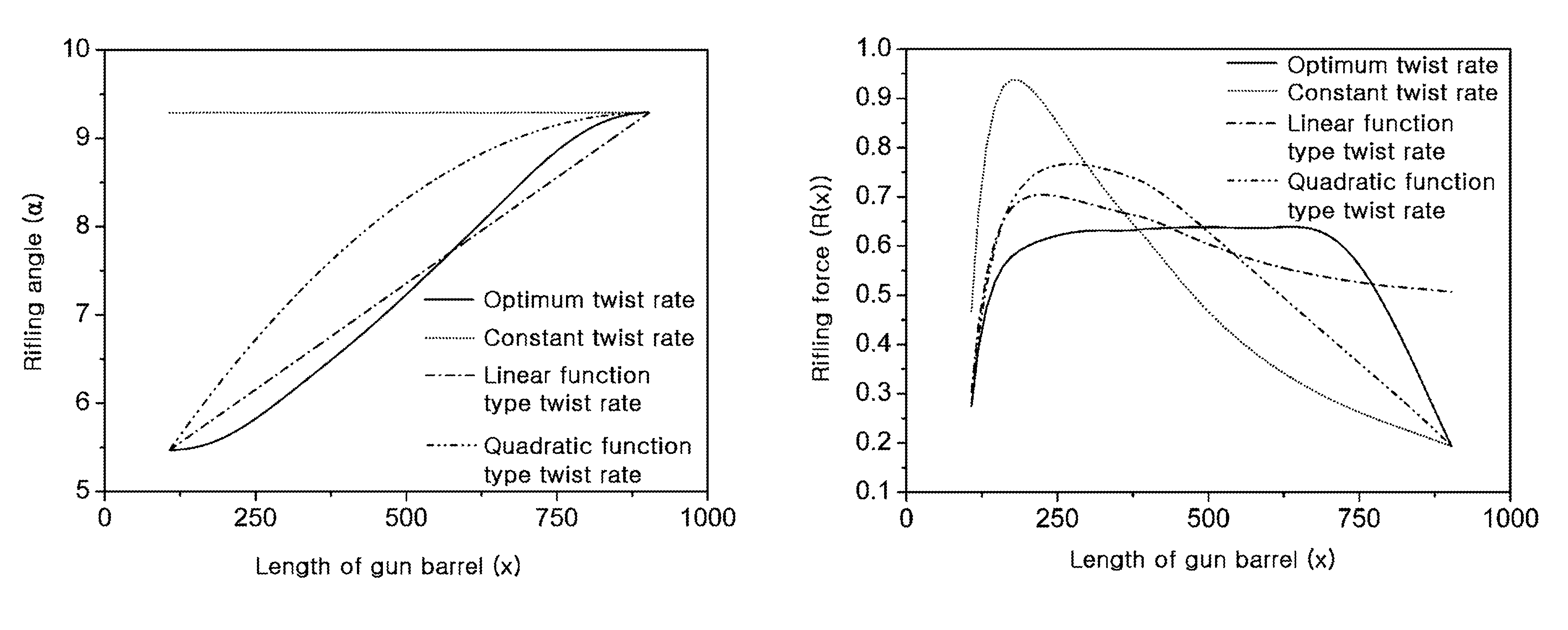
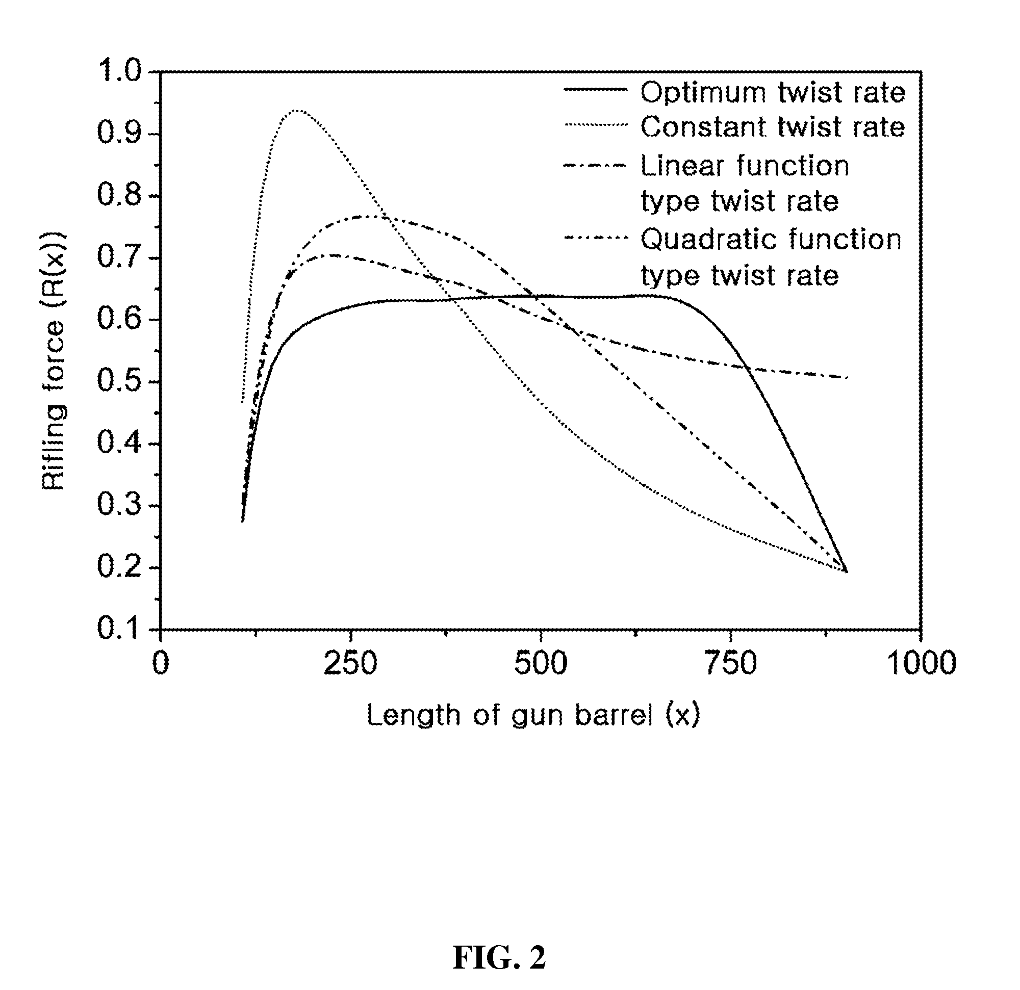
[0011]Accordingly, the present invention has been made in view of the above-mentioned problems occurring in the prior art, and it is an object of the present invention to provide a rifling angle calculating method capable of minimizing the maximum value of rifling force generated when a gun is fired.
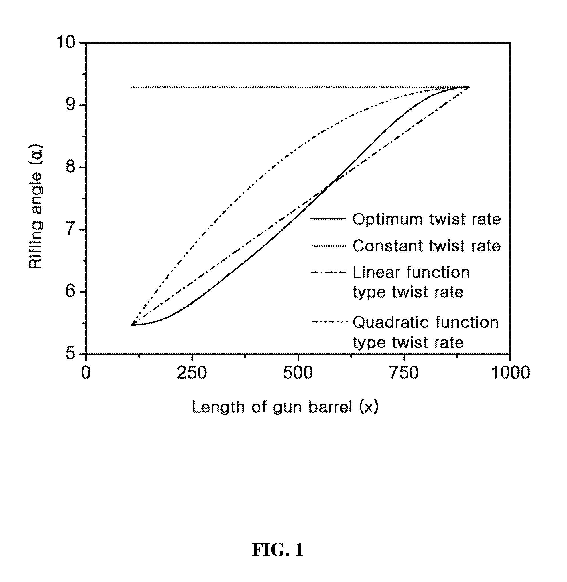
[0013]To accomplish the above objects, according to an aspect of the present invention, there is provided a rifling angle calculating method, in which rifling angle α(x), i.e., a parameter of rifling force, is calculated by expanding the rifling angle into a mathematical expression shown below in order to minimize a maximum value of the rifling force generated between a projectile and rifling when the projectile moves along an inner surface of a gun barrel by gun barrel pressure.

Problems solved by technology

However, since rifling force generated by the designed rifling shows a maximum value locally, or a big rifling force appears at the time point when a projectile departs from the muzzle of a gun, the lifespan of the gun barrel or flight of the projectile may be negatively affected.
However, if the rifling angle is expanded only into the Fourier function, convergence is guaranteed as the number of terms is increased, but it is disadvantageous in that boundary conditions cannot be satisfied.

Method used


Image

  • Rifling angle calculating method
  • Rifling angle calculating method
  • Rifling angle calculating method

Examples


Embodiment Construction

[0023]Rifling is a depressed and prominent part processed on the inner surface of a gun barrel in order to impart a spin to a projectile, which refers to a part protruding from the inner surface of the gun barrel. At this point, a hollow part formed by the protruding rifling is referred to as a rifling groove. An action force generated between the projectile and the rifling when the projectile moves along the inner surface of the gun barrel by gun barrel pressure p(x) is referred to as rifling force R(x) and can be theorized as shown in mathematical expression 2.

[0024]⁢[Mathematical⁢⁢expression⁢⁢2]R⁡(x)=4D2⁢Jpmp⁡[ⅆyⅆx⁢P⁡(x)+ⅆ2⁢yⅆx2⁢⁢v⁡(x)2⁢mp]

[0025]Here, P(x) denotes action force generated by gun barrel pressure p(x), which is expressed as

[0026]P⁡(x)=p⁡(x)⁢(π4⁢D2+nbt),

where x denotes a distance along the length of the gun barrel from a gun breech, y denotes a shape of a rifling angle, D denotes a rifling slope, mp denotes mass of a projectile, Jp denotes mass moment of inertia of a ...


PUM


Abstract

A rifling angle calculating method according to the present invention expands a rifling angle by combining a Fourier function and a polynomial function to take only the advantages of the two functions, and thus boundary conditions at the start and end points of the rifling angle may be faithfully satisfied, and an optimum rifling angle for minimizing the maximum rifling force may be calculated.

Description

CROSS REFERENCE TO RELATED APPLICATION[0001]This application claims the benefit of Korean Patent Application No. 10-2011-0009566 filed Jan. 31, 2011, the entire disclosure of which is incorporated herein by reference.BACKGROUND OF THE INVENTION[0002]1. Field of the Invention[0003]The present invention relates to a rifling angle calculating method, and more specifically, to a rifling angle calculating method capable of minimizing the maximum value of rifling force generated when a gun is fired, by expanding the rifling angle into a function of length of gun barrel.[0004]2. Background of the Related Art[0005]A rifling angle α is an angle expressing a shape y of rifling along the direction of length x of a gun barrel, which can be expressed in mathematical expression 1 shown below.[0006]tan⁢⁢α=ⅆyⅆx[mathematical⁢⁢expression⁢⁢1][0007]Conventionally, rifling is designed by stabilizing twist rate[0008]ⅆyⅆxin the form of a linear or quadratic function. However, since rifling force generated...

Claims


Application Information

Patent Timeline
Patent Type & Authority Patents(United States)
IPC IPC(8): F41A21/18
CPCF41A21/18
Inventor CHA, KI UPLEE, YOUNG HYUNCHO, CHANG KI
Owner AGENCY FOR DEFENSE DEV
Why Eureka
Try Eureka